|
Building a 1:144
Scale Radio-Controlled USS Nimitz:
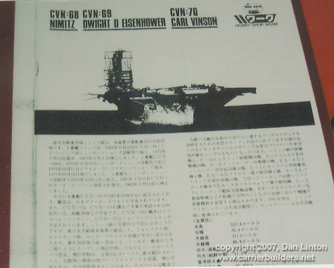
I was very fortunate, more than 15 years ago, to order a very curious item from Japan. Companies such as LS, Otaki, and Arii produced and were producing large numbers of 1:144 scale aircraft kits -- F-14, F-18, F-4's and F-8's in particular, as well as RA-5C Vigilantes, and then with DML/Dragon, A-6's and EA-6B's. Someone in Japan had the bright idea of creating a Nimitz superstructure in 1:144 scale to allow a modeler interesting diorama possibilities. Producing a resin, or even an injected molded superstructure would make no economic sense, so 'Hobby Shop Work' created the superstructure on paper -- heavy bond, pre-painted 17"x11" (43cmx28cm) sheets. There were 13 of these and they allowed one to build a Nimitz, or Eisenhower, or Vinson superstructure and rear radar mast using simply scissors and white glue. The instruction pamphlet is 31 pages long (see Picture 1). I photocopied the sheets and the instructions: later I would send the originals back to Japan to Yuuichi Kurakami (Mini-Scale Wings: see Part II of this build article) to thank him for all the help he gave me. His response was interesting: " I had heard that this existed, but had never seen it". Using photocopies one can translate paper into styrene and this is what I did for this build.
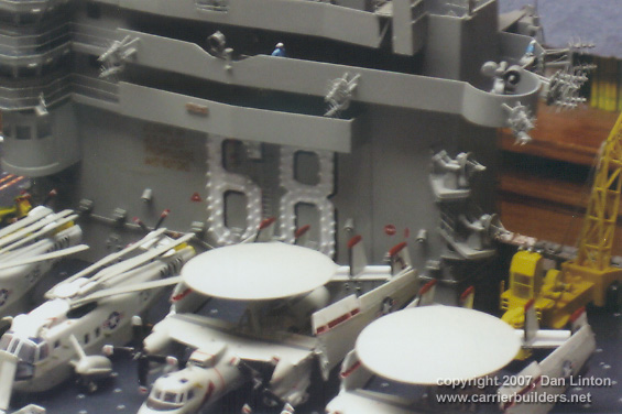
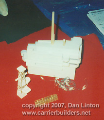
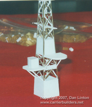
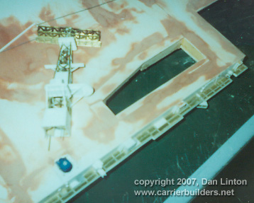
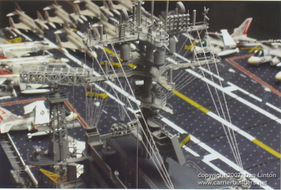
Picture 2 shows the early superstructure and radar mast. I don't have pictures of the very early phase of construction. I purchased 'grain of rice' bulbs' and installed 18 of them in the bridges and pri-fly areas (seen later) but should have put one inthe t.v. pedestal. I assumed that I would have room to use fibre optics for lighting up the number '68' on both sides of the island (a mistaken assumption as it turned out). The interior of the bridges and pri-fly areas were done with instruments, chairs, and even bulletin boards on the bulkheads, but my efforts with clear plastic were so poor that little can be seen. Picture 3 shows the radar mast early in its construction. It is made of styrene and brass: up through the middle of the entire structure a piano wire was later placed to attach one end to a large radar (SPS-43A) and at the other to a small motor embedded in the flight deck (see the blue circle in Picture 4.)
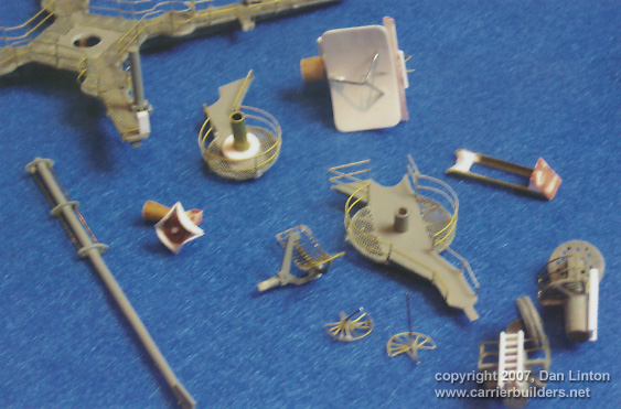
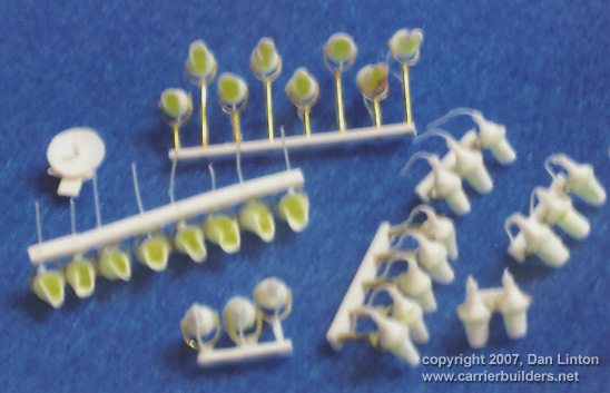
Picture 5 shows the SPS43A. It is entirely made of brass.
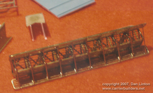
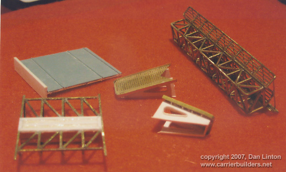
Picture 6 shows the back of the SPS-48A
Radar and its support (styrene and
brass) and the two platforms for the aircraft approach radars found at the aft
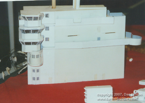
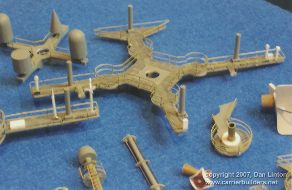
end of the superstructure. Picture 7 shows the superstructure before any details
were added and Picture 8, taken at
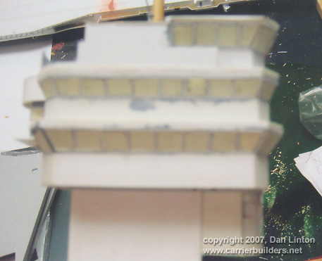
Picture 9 shows all the 'glass' in the superstructure covered with 'Stik-It' paper --- an incredibly tedious job --- to prepare the superstructure for spray painting. Once that was done, then details could be added.
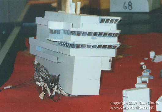
he superstructure, with bundles of wires sticking out, kept falling over so a simple wooden support structure was built. This is seen in Picture 10.
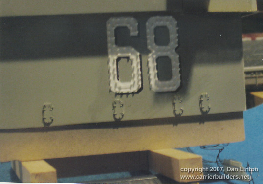
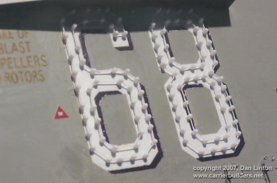
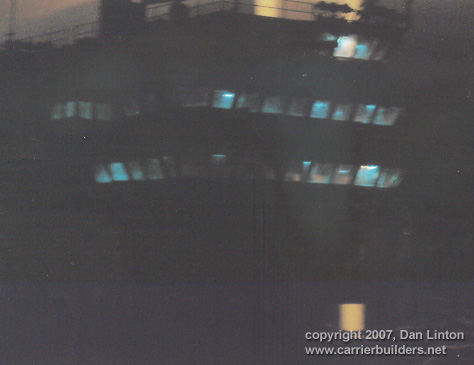
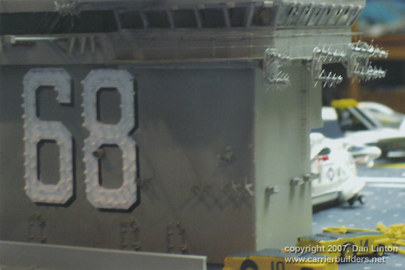
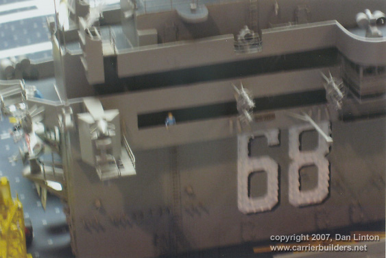
Here the superstructure has been painted, decals added, and the lights for '68' put in place. Poor planning on my part resulted in not being able to light up these numbers, not even using thin fibre optics. There simply wasn't enough room to bunch 105 fibres on each side plus light bulbs, plus connectors. As well,depicting the ship for the 1975-82 time period played a role. When commissioned in 1975 Nimitz had no lights for her numbers, they seem to have been added in 1977. When added, they formed a double row at the edges of the numbers, as seen in Picture 11.
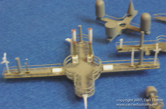
Interestingly, later in her career
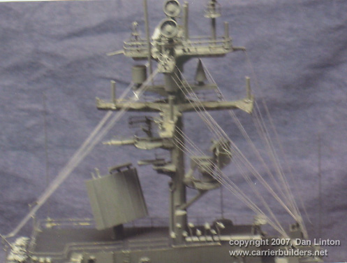
and certainly when she transferred to the Pacific Fleet Pictures 12, 13, and 14 show various radars, receivers, and support structures that are part of the mainmast. t the bottom right of picture 12 are the satellite receivers and supports. Picture 13 shows the main cross spar and picture 14 (a bit blurry) shows the top cross spar.
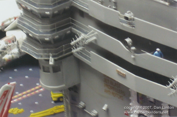
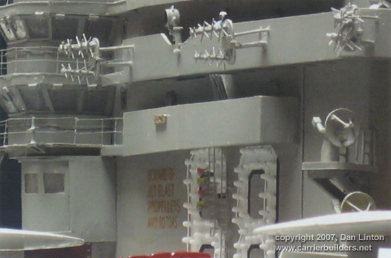
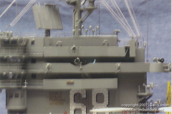
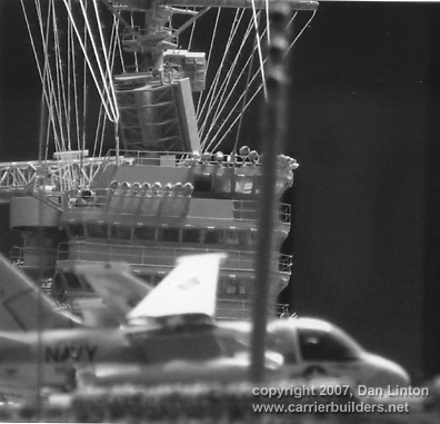
Picture 16 shows a large number of floodlights, larger than those in the earlier picture, that are placed along the top deck of the superstructure.
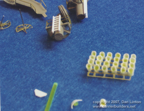
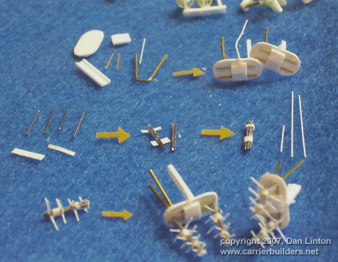
Picture 17 shows the construction sequence for what are apparently radio receivers and transmitters. There are twelve of these located around the superstructure and the picture shows two completed ones at the bottom. These were absolutely the most tedious of all the pieces I had to make. And they are not accurate -- there should be six rows of spikey projections on each antenna instead of the four seen here -- but I really lost the heart to try and redo all of these.
Picture 18 is a demonstration of my
poor skills as a cameraman: the lights are actually brighter than they
Picture 19 shows most of the port
side of the superstructure and picture 20 shows more details. The
Most of the entire ports side is seen in picture 22 and the front of the superstructure is highlighted in picture 23.
Picture 24, a bit blurry, shows the starboard and rear of the superstructure.
Picture 25 shows clearly that white
thread was used for the rigging. I have pictures taken on the USS Abraham
Lincoln (CVN -72) that clearly shows the rigging is made of rope, not wire, and
that the rope initially is white. Fine lint fibres will always come off thread
and I had initially considered mixing white glue and
Picture 26 shows the rigging to good effect: it is however, quite delicate and I am surprised it has held up as well as it has.
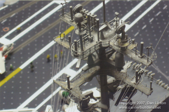
Picture 27 shows the mainmast and its spars from the rear while picture 28 shows the same from the front: interestingly, the forward SPS-48A radar (it rotates as does the radar on the tower mast) is not sitting properly: it needs a slight twist to fall ¼" (60mm) into its proper place. This was done after the pictures were taken.
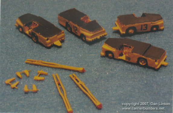
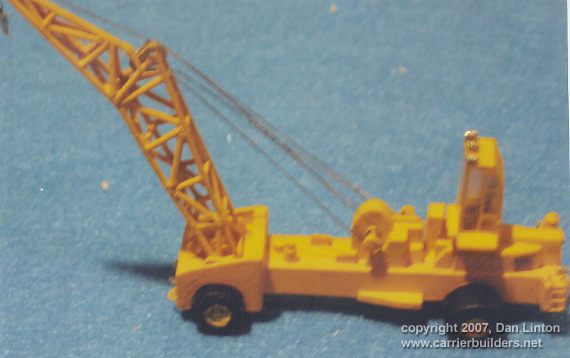
Work on the superstructure was often interrupted (particularly when it got tedious) by directing attention elsewhere. Picture 29 shows wheel chocks (wire and styrene) at the left next to tow bars (mostly brass). I made two dozens sets of chocks and over thirty tow-bars. Two styles of tractors can be seen here: number 12 came with a 1:144 aircraft kit. I have two of these and scratch-built another dozen. All have lead sinkers (used by fishermen) on the underside to prevent the tractors from being blown off the flight deck. I built a beautiful-looking Tilley, taking two full days to complete it only to discover it was too small. How I screwed up so badly I don't really know but it forced me to build the one you see in picture 30: not quite as attractive, missing here its exhaust stack, but at least of appropriate size.
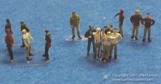
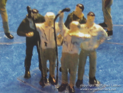
Picture 31 shows some crew figures, taken from Preiser's 1:144 NATO pilots and ground crew kits. Each contains 18 figures. Almost all have to be modified and many arms and legs had to be 'broken' and then reset. I had about 95 crew to work with and since I did not want to glue them permanently to the flight deck, I needed a way of having them stand up. Thin clear plastic, the type often found inside the collars of new shirts, was used. Neither traditional glue for styrene nor super CA glue works well (flick any of these figures, even gently, and they will fly) so these need careful handling. And since these are plastic and not white metal, I fear that even the gentlest breeze will send them flying over and off the flight deck. Picture 32 is a close-up of a small diorama that will take place at the LSO platform (to be seen in a picture in Part VIII).I painted the uniforms but balked at trying to do eyes, mouths, and noses.
So with the superstructure done, the
model is essentially finished. And as with all large projects, there are lessons
to be learned. And that will be the subject of Part VIII of this build article.
End of Part VII.
Go to: Photos and text © 2006 by Dan Linton January 30, 2007 |