|
Building a 1:144
Scale Radio-Controlled USS Nimitz:
Many years ago, 1982 or 1983, I purchased a Monogram USS Nimitz plastic model
kit. It was 16" long (roughly 1:800) and I ignored it for a while, finally
giving it to my youngest son to complete.
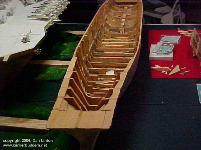
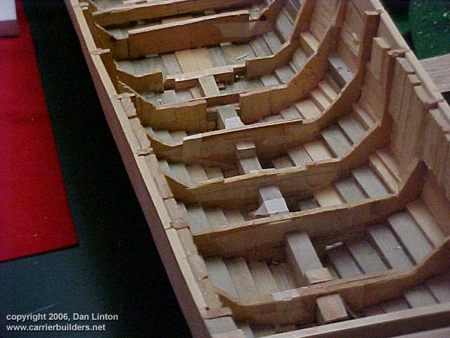
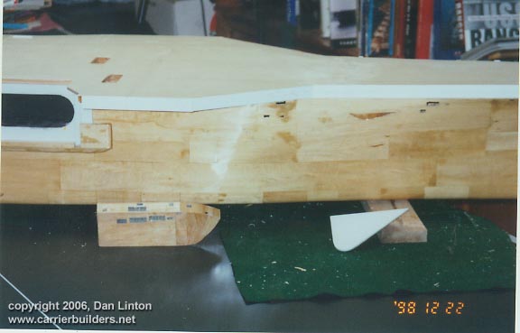
Pictures 1 and 2 show the type of hull I am referring to - pine on pine. The hull shown is not the Nimitz but the Ranger (CV-61), a project for the future. Once I completed the rec room of our new house five years ago, I set up a temporary (= summer months) workshop in the garage and went crazy building hulls. The furthest along of these hulls are the Ranger that you see and another Ranger (CV-4). When the fall came, and it was too cold to work in the garage, the Nimitz air wing got most of my attention. Next spring, back to the hull. This explains why the air wing was finished long before the ship. A pine hull over 85" (over two meters) long is very heavy but I did want something rugged.
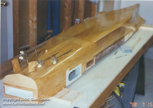
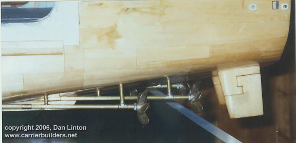
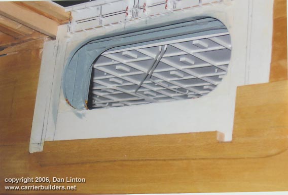
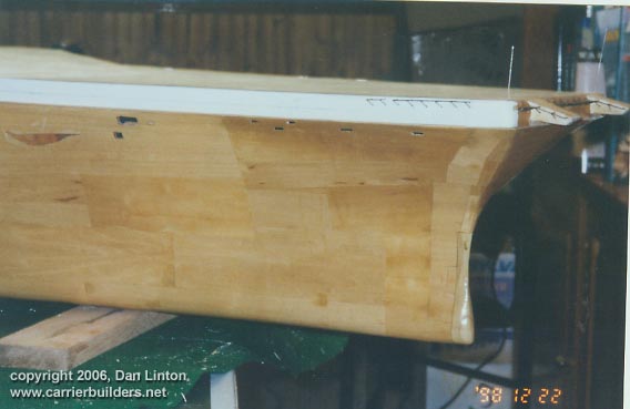
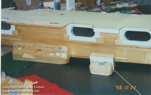
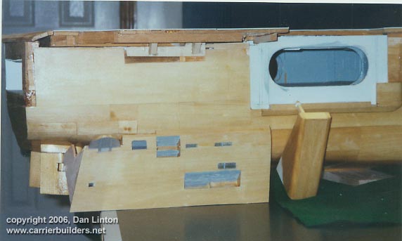
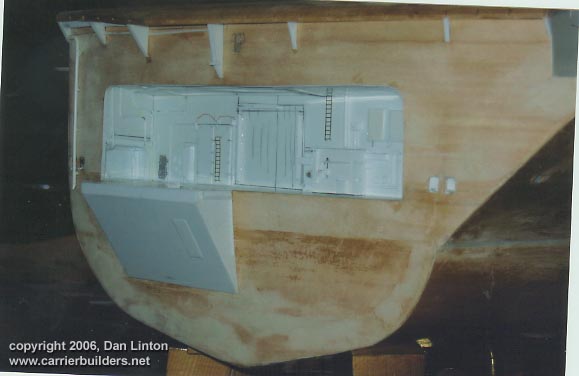
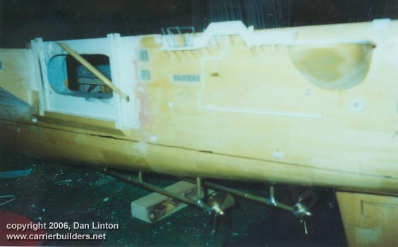
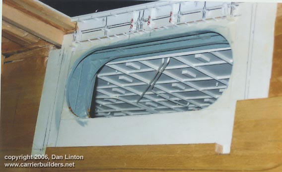
Picture 3 shows the Nimitz hull with 1/32 basswood sheathing, sanded and varnished, except at the stern. Bilge keels have been added, rudders, propellers, and shafts are installed. This is seen in more detail in Picture 4. The white area defining an elevator opening to the hangar deck was a separate construction and added to the hull (Picture 5). The white is styrene sheathed onto pine. The dark brown area of Picture 3 will be hidden when the port-side sponson is added on.
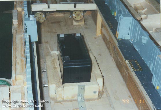
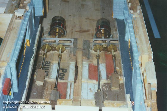
Picture 6 shows the 12-volt battery which serves the two motors that drive the four shafts. (Picture 7).
The above series of pictures show the starboard side of the ship
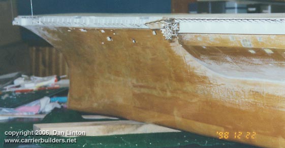
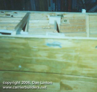
before various sponsons were added. Picture 8 shows the forepeak but as
yet many cut-outs, including the hawse pipe for the anchor,
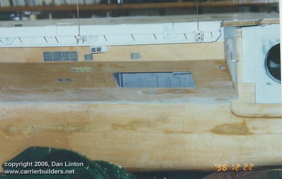
Picture 10 shows the sponson between elevators #1 and #2, and the area under the island.
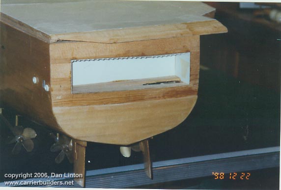
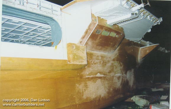
Picture 11 shows the crane support and rear sponson on the starboard side. Picture 12 shows the stern and it is a mess. Errors in measuring that original Monogram kit showed up here -the stern opening was too high, not level, and the roof section was inaccurate and had to be torn out.
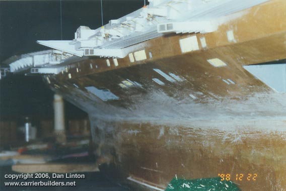
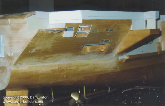
Pictures 13,14,15,and 16 show the portside sponson installed in place. The sanding marks show that another coat of varnish will be necessary before painting can begin.
Picture 17 shows the installation of the foreward starboard sponsons and the accompanying sanding marks.
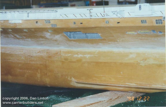
Picture 18 shows the sponson between the forward elevators. Picture 19 shows the sponson under the superstructure and Picture 20 shows the crane support and rear starboard sponson in place.
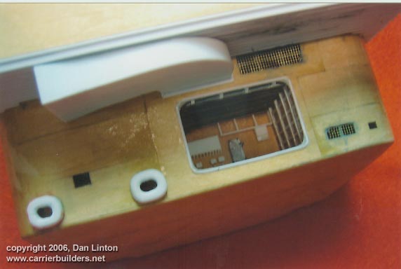
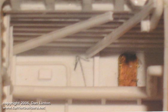
And Picture 21 shows the stern: it is no longer an embarrassment. Picture 22 is somewhat blurry but it attempts to show the inside of a refueling/replenishment station. There is much more detail to add but it makes no sense to do so until some painting is done.
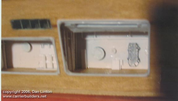
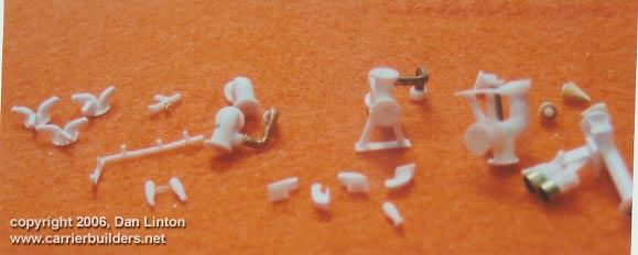
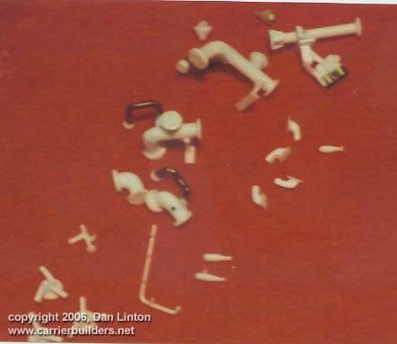
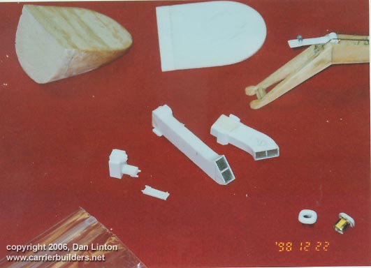
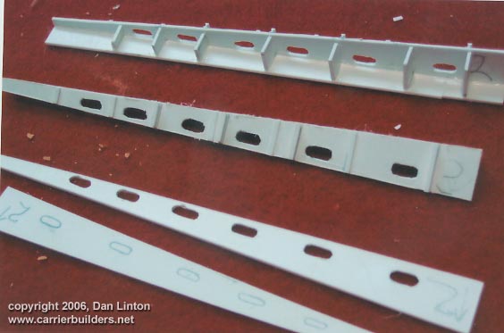
Picture 24 and 25 show pieces that go into other stations. Picture 26 and 27 show other structure (BPDMS launchers in Picture 27) that will be added once painting is done. Ships boats, accommodation ladders and supports, and the rear portside exterior walkway must also be completed.
Picture 28 is fuzzy (my digital camera was broken and I had to use a disposable for some of these shots) but the brass I-beam sticking out from the hull goes under and supports a part of the flight deck called 'the finger'. It has been made removable by hand so that when the flight deck is removed, it too can be taken away from the hull. The anchors (not seen) are white metal from John R. Haynes. I was able to have the flukes on one (but not the other) rotate on its shaft. This anchor, on the port side, can be positioned fully up or in any position down (almost ½ meter of anchor chain).
By removing a screen (the grey are in fuzzy Picture 29) on the portside forward
hull a screwdriver can be inserted to twist a dowel (just visible) which will
raise or lower the anchor. American CV's and CVN's usually lower the port anchor
halfway to the water when
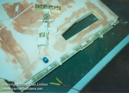
Picture 30 shows the area above the hangar deck opening but below the flight deck. There are tubular structures here and narrow catwalks (handrails to be installed after painting this area). The tubular structures have a steel extensions (seen here in part as lengths of piano wire) which push upwards and force a horizontal railing out of the flight deck as the elevator goes down, thus creating a safety railing for flight deck crews. When the elevator goes up, this railing retreats into the flight deck.
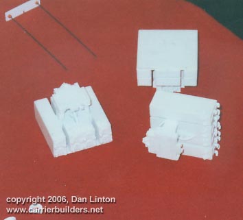
Picture 31 shows the beginning of construction for the elevator support structures. Interestingly, and most irritatingly, these were too large and had to be narrowed considerably. The amount of detail I have provided/am obliged to provide is light years away from what I anticipated when I started this project. The credit for this (and perhaps the blame for extending the time taken) goes to three gentlemen: without their involvement I would certainly had much less satisfaction in this build. The first of these gentlemen is Tim Barron. He sent me hundreds of pictures he had collected from US Navy websites and dozens of those pictures were absolutely vital in allowing me to clearly see details that would otherwise be obscure. Tim has created an excellent diorama in 1:2400 scale and I would urge you to go to our membership list and click on his website. The second gentleman is Kurt Greiner. Kurt is the webmaster of WarshipModelsUnderway and as a business runs Sea Photos. He was very helpful in selecting shots that I needed, particularly of sponsons and the underside of flight deck overhangs. The pictures I purchases from him were well worth the money.The third gentlemen is Ray D. Bean whose two CD's, one on the Nimitz class and the second on the Nimitz after its mid-life refit, have to be one of the great bargains on this planet. It would be great if every carrier had a CD put together by Ray. Because my computer is upstairs, and the model is downstairs or in the garage, the CD is less flexible for me than the pictures: on the other hand, the CD shots can be expanded greatly on the computer screen, adding new dimensions of detail and of understanding what one is seeing.
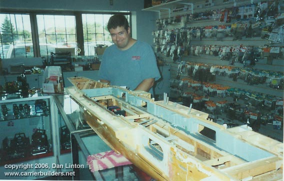
There is a fourth gentleman who must be acknowledged in this article. His name is David Henry and he is the fellow in Picture 32. David works at Pinnacle Hobbies, 5970 16th Ave, Markham, Ontario (pinnaclehobby@rogers.com), a shop north-east of Toronto. Besides being reasonably close to where I live (11 km/ 7 miles), Pinnacle Hobbies specializes in radio-control. Their main business is cars and aircraft, but their forte is radio-controlled helicopters. Putting RC into a ship is a piece of cake for these men. On Wednesday, Sept.7, 2005, I brought the Nimitz hull to Pinnacle Hobbies at 10:00AM. It was put, as you see in the picture, on top of a glass counter and Dave went to work - and of course, customers came into the store, so working on the hull was done in fits and starts. By closing time, 6:00 PM the main effort was complete.
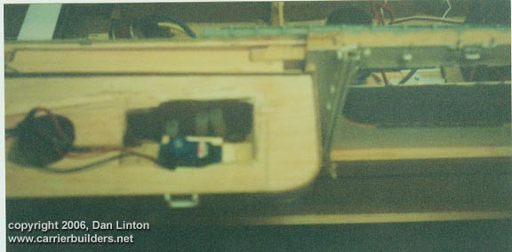
Control of the rudders and propellers for speed and direction is basic but added is a radio channel which causes a servo arm to move a toggle switch - and this provides power to two micro-motors (the blue areas in Pictures 33 and 34) that rotate radars at 20-30 rpm. There is a switch hidden under the sponson below the superstructure and beside it is a plug that allows the main 12-volt battery to be re-charged without having to remove the flight deck. Dave went out of his way to make everything as convenient as possible for me. Thank you David.
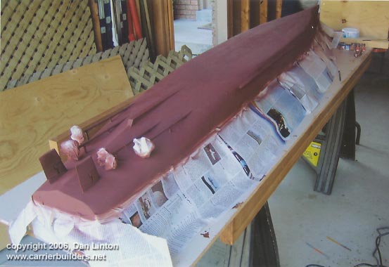
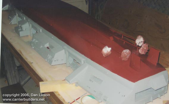
Pictures 35 and 36 show the hull being painted in the garage. White Ensign Model (WEM - one of our sponsors) naval paints were used throughout. The red spot seen in picture 36 inside the sponson that is under the superstructure, is the switch mentioned in the previous paragraph. And picture 37 is the spray booth I built out of plywood. The black lines are wires that are adjustable so pieces of different sizes can be hung, painted and left to dry. The white area in the upper left of the picture is a side door into the garage: when the main garage door is open, the flow of air through this side door provides excellent ventilation. The small parts shown earlier, handrailings, and decals remain to complete the hull. Meanwhile, work continues in other areas.
End of Part V.
Go to: Photos and text © 2006 by Dan Linton March 22, 2006 |