|
Building a 1:144
Scale Radio-Controlled USS Nimitz:
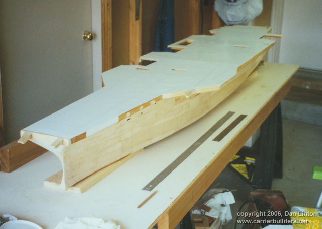
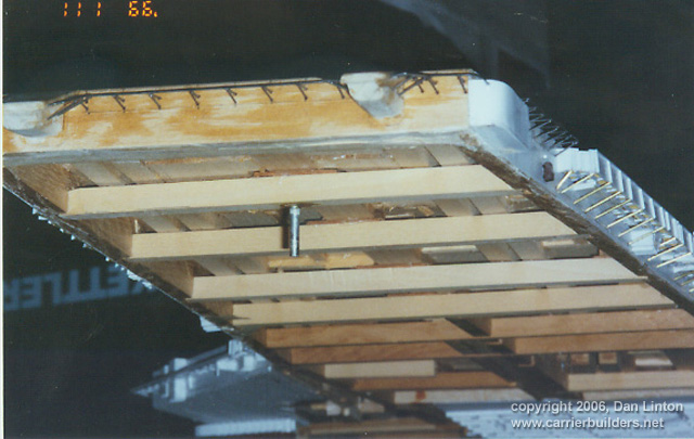
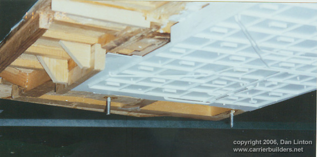
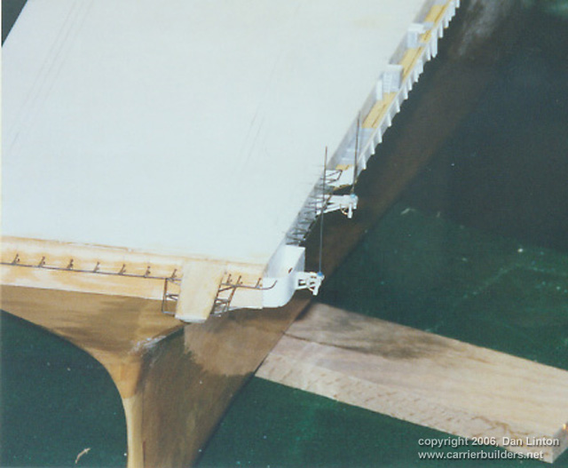
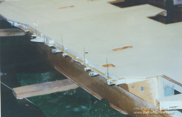
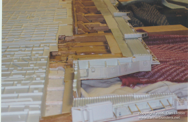
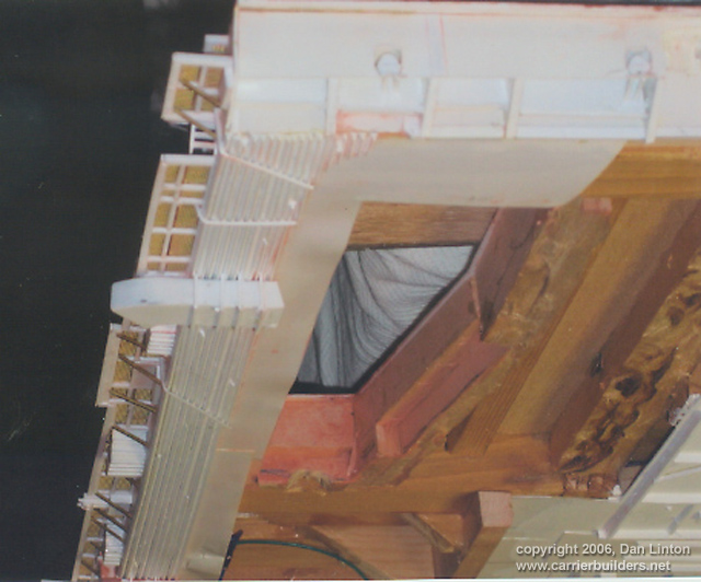
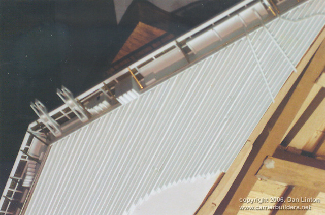
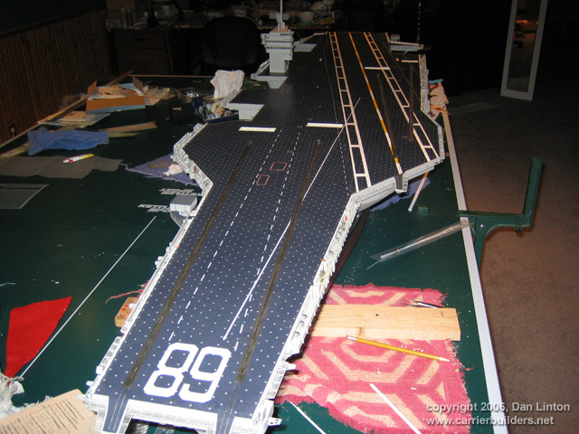
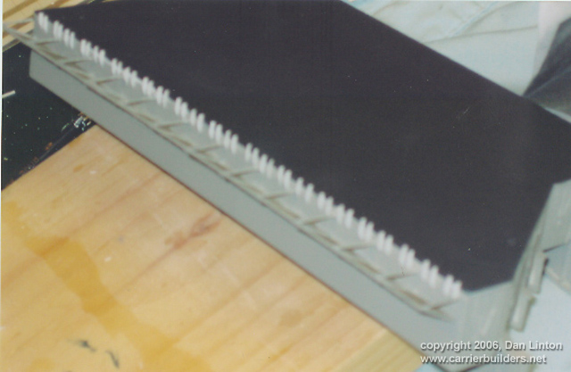
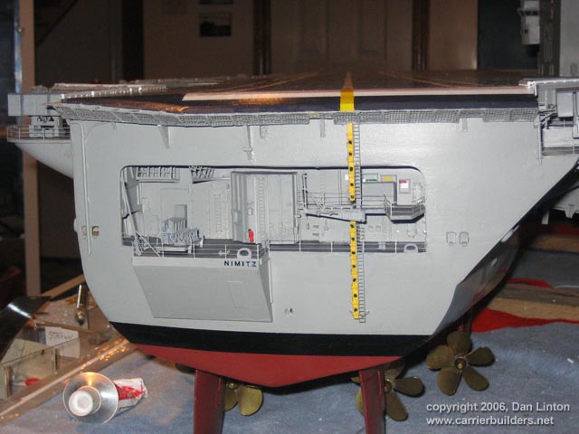
The flight deck, all 91” (2.3m), was built to be removed as a single piece from the hull. It was one of the earliest parts of the ship – a pine frame with balsa wood filling in the gaps and all covered with 40/1000 styrene sheet. It had to flex but only a tiny amount. Two-part epoxy resin was used to attach the styrene to the wood and it has held up very well over the years. There are six large pieces that cover the deck (see Picture 1) with cut-outs for the elevators and jet blast deflectors (JBD). Picture 2 shows the underlying structure of the flight deck at the bow. The very front of the flight deck is not pine but maple, a hardwood, and the catapult extensions (Nimitz was built with three) are also maple. Some glue was used to hold the catapult extensions to the flight deck but what cannot be seen is that thick wood screws have been used to secure these pieces. To lift and lower the flight deck, fingers are used under these extensions. Removing and then putting back the entire flight deck at one time requires accuracy, otherwise too many pieces will break off along the catwalks and the elevators. That is why the single metal piece is seen in Picture 2, while two are seen in Picture 3: these metal pieces fit into exact-sized holes in the hull cross-framing.
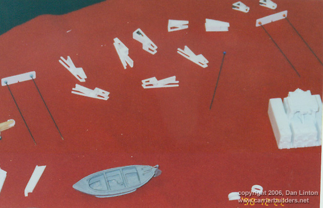
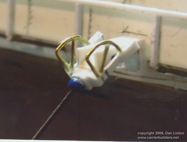
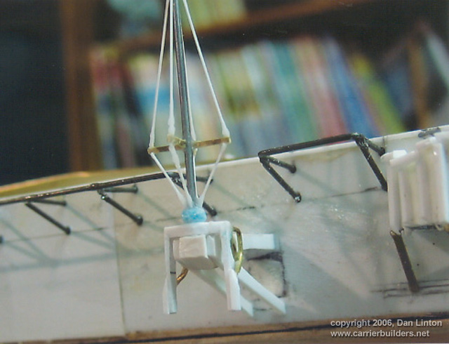
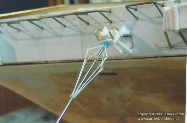
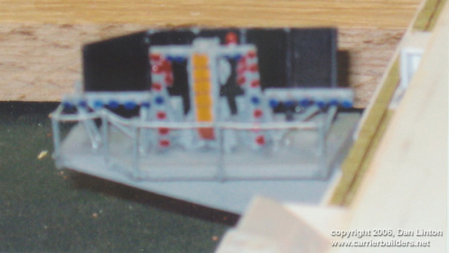
Picture 4 shows some antennas and their support structures and Picture 5 shows two of them in place at the edge of the flight deck near the bow. These antennas gave me no end of trouble. Pictures 6, 7, and 8 are close-ups. The style of antenna that the Nimitz had early in its career (and all USN carriers from the mid-1950’s to the 1980’s) have balance horns – the projections the brass wire is glued onto – which rotate with the antennas. To get the antennas to rotate inside the support structure while the balance horns rotated at the same time outside the same support structure was a challenge, particularly when they had to be made removable when the model was being transported. Actually, “that was a challenge” is a rather lame way to describe my feelings: more truthful would be to admit that I lost ¼” (.65mm) from my teeth for all the grinding they were doing. Picture 9 shows some of the antennas on the port deck-edge. Picture 10 (I apologize for the blurriness) shows the ‘meatball’ or mirror landing system. It is glued to its support but that support structure is itself removable.
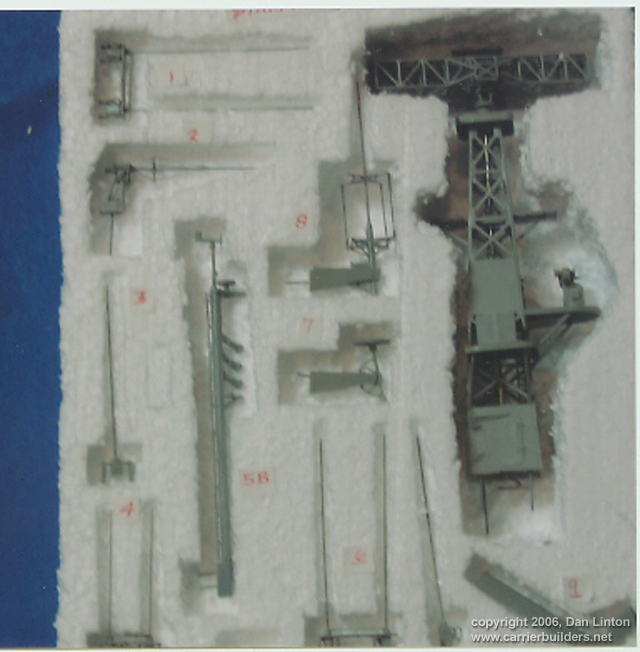
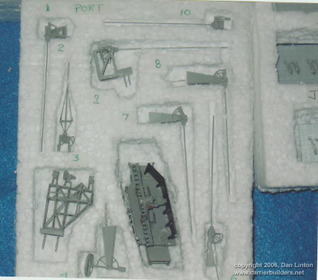
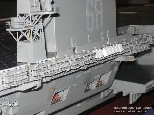
More than twenty structures have to be removable. Picture 11 shows a styrofoam block with cut-outs for structures on the starboard side of the ship. The main radar tower is to the right and the long thin structure labelled as ‘5B’ is the ‘Belknap’ pole. In November, 1977, the USS Belknap (DLG-26) collided with the USS John F. Kennedy (CV-67), passing under the carrier’s portside overhang. The destroyer’s light alloy superstructure was no match for the carrier’s steel and the superstructure, funnels, masts, just about every structure above the main deck was sheared away. To aid in judging distances at night, a tall pole with lights on it was installed on all USN carriers on the forward flight deck edge parallel with the island. The Nimitz was put into service before the accident but had the pole by 1983. QUIZ: did the Nimitz have a ‘Belknap pole’ (sometimes called a ‘Kennedy pole’) when The Final Countdown was made? Picture 12 shows the various portside antennas, including the ‘meatball’, inside its styrofoam block.
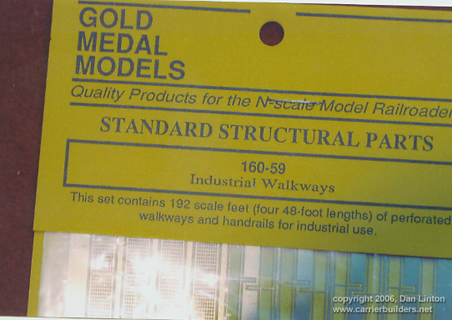
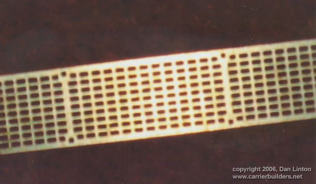
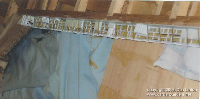
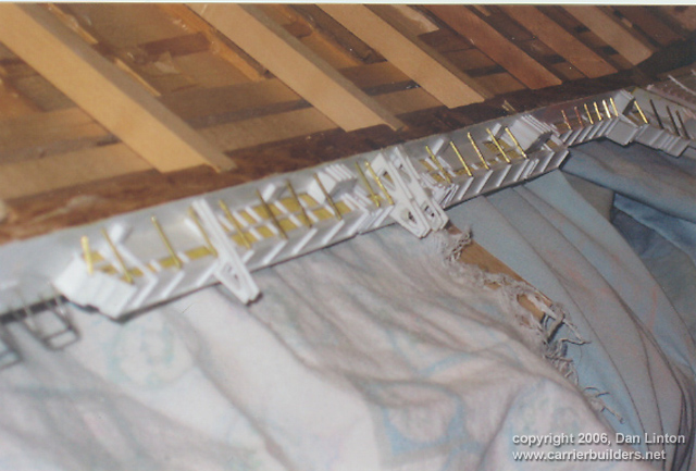
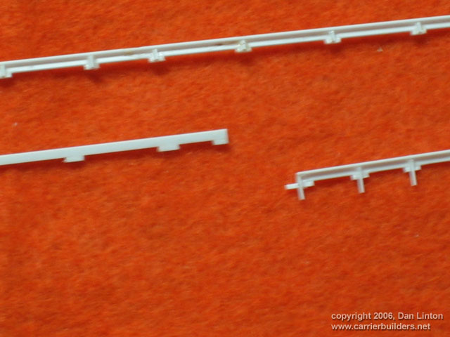
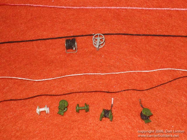
Radio-control equipment, motors, shafts, lights, and propellers are expensive items and I expected to part with many shekels to buy them. What I did not expect was the cost involved in walkways! Pictures 13 and 14 show what I used. While photo-etch (PE) frets of walkways exist for 1:350 carriers and some 1:700 scale carriers, there is nothing in 1:144 scale. The closest I could find was Gold Medal Models 160-59 Industrial Walkways (Picture 13) designed for N-scale (1:160) railroad models. Notice there are only four lengths of walkways and 48’ in 1:160 is only 43’ in 1:144: the Nimitz is 1092’ long and to be accurate, most of the catwalks are twice the width of the GMM Industrial Walkways – we are talking a major expense here. I will not provide more details here in case my wife reads this – fear is an honest emotion. Picture 14 shows the particular grating pattern I was looking for. Pictures 15 to 19 show many of the catwalk structures seen from underneath.
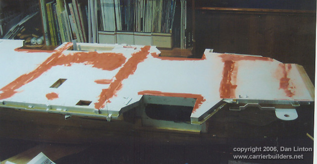
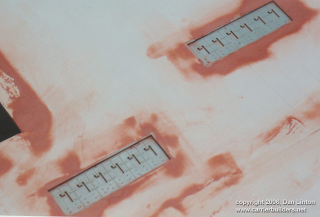
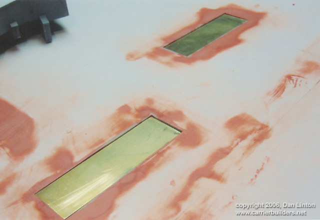
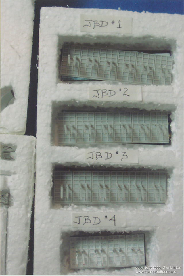
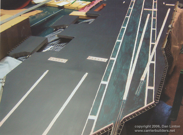
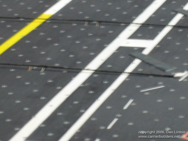
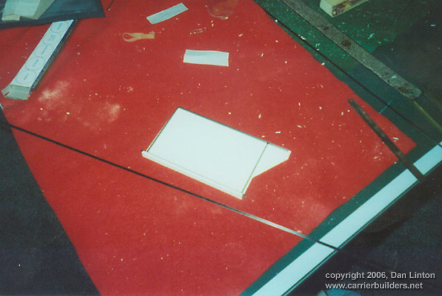
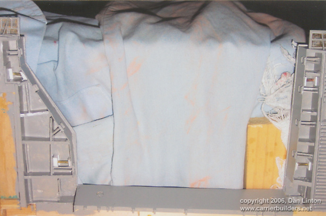
Picture 20 is revealing, proof that a perfectly level surface was not achieved. The red material is Bondo, an automotive filler material which spread smoothly, dried quickly, and sanded very well. Dragon models in the late 1980’s produced a series of 1:144 scale aircraft kits (still available). One kit, ‘Blast Off’, with an F-18, and another, ‘Launch’ with an F-14, provided not only the aircraft but also some deck equipment and crew, and a section of the flight deck which included a jet blast deflector (JBD). On another page of this website, the Naval Aviation Gallery, scroll down and check when it reads ‘scale 1:144’. That is the fastest way to find Paolo Yuen’s F-14 and Roberto K. Musakawa with his E-2C who have used these kits. Picture 21 shows that I used the base of the kit-supplied JBDs and put four of them in the Nimitz. Since I wanted to be able to display each JBD in an up or a down position, I made JBD plates from flat brass (30/1000), a heavy enough material that there would be no blowing away in a moderate wind (see Picture 22). The extended JBD’s from the kit (seen in their styrofoam cut-outs in Picture 23) are too light for use when the model is on a pond. Picture 24 shows the deck being painted: the hull was airbrushed when in the garage but by the time I was ready for the flight deck is was too cold and so the model was inside the house and so hand-painting. Picture 25 shows the flight deck with its decals applied, including 2500+ tie-down pad decals from Mike Grant Decals. They had to be applied one at a time. The deck is still glossy but in Picture 26, unfortunately blurry, it has been sprayed with Testor’s Dullcote and arrestor wires, springs, and pads have been added. I will not be weathering this model (to be explained more fully in Part VIII).
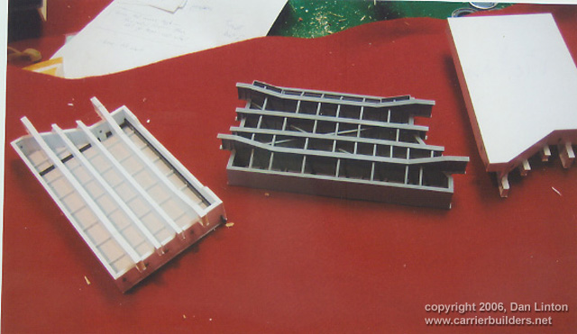
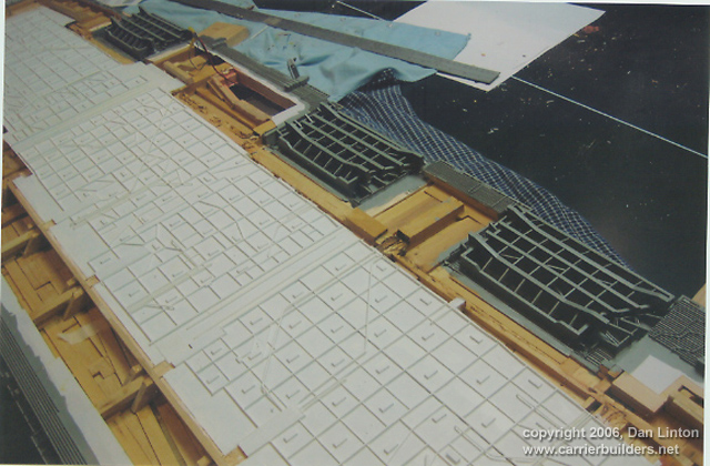
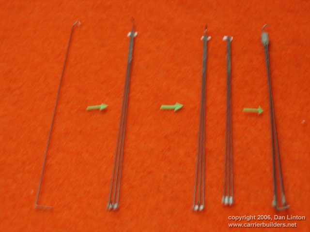
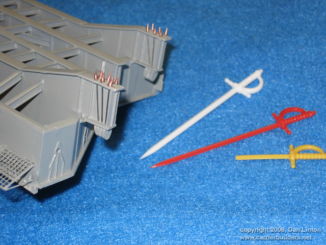
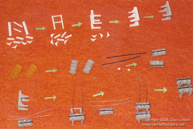
Carriers cannot function without elevators and all USN carriers from the cancelled USS United States (CVA-58) to CVN-77 (George W. Bush) have been designed with four deck-edge elevators. Operational experience over a half-century has convinced the USN that only three elevators are necessary so CVN-78 will have only three. This means more permanent flight deck parking space. Normally, American CVN’s have only 15-20 aircraft in the hangar deck (a maximum of 45-50 could be squeezed in but little effective maintenance could be done) so aircraft on the flight deck have to be ‘spotted’ and ‘respotted’ repeatedly. Picture 27 shows the beginning of an elevator’s construction. The long black material is carbon fibre that I picked up at Pinnacle Hobbies because it provides great stiffness and rigidity with low weight. Picture 28 shows three elevators in various stages of construction. Picture 29 shows the flanges that hold a kickplate or large metal piece used to prevent sailors from slipping of the edge of the elevators and flight deck. These are seen in Picture 30. Picture 29 also reveals why this project took so long – there are 48 flanges on each elevator. I actually started to try to count the number of pieces in each elevator but stopped once I reached 350. And it gets worse. Picture 31 shows the underside of an elevator opening: where you see white styrene and brass rod is where the elevator cables go. On CVN’s , the elevators are supported by six steel cables from each of the four locations in Picture 31. The next picture, 32, shows the three starboard side elevators ready to receive cables. Picture 33 shows the process of cable construction: it starts with a single wire with a tight curved bend at the top to fit around the small brass rod seen in Picture 31 and an ‘L’-shaped bend at the bottom. Two small styrene cross- pieces are added and then two more wires, but these have neither curve nor ‘L’ shape at the ends. This is the first half of the cable assembly. The process is repeated only the second half assembly does not have a curved bend. The two halves (3 cables each) are then joined at the top facing each other but not at the bottom: the wires have just enough flex at the bottom that they can be opened up slightly and the ‘L’ bend part of the wire slips into a slot in an elevator piece thus holding it up. Altogether, 16 cable assemblies – that’s 96 wires! All these wires can be seen in their styrofoam cut-outs if you skip ahead to Picture 47. Because of less than perfect planning on my part, not only do the cables for the #1 elevator have to be kept separate from all the others, but each of the four cables for elevator #1 can only go in one specific spot – if not then the elevator will not be parallel with the flight deck. The final bit of madness involves the area where the cables tie into the elevators. This is shown in Picture 34. Each of the 24 cables for each elevator ends with a pointed metal tie-off. The closest approximation of this were the plastic tips of tiny swords to spear olives or cherries in mixed drinks. Wooden toothpick tips are too likely to split and/or get blunted. I bought two packs (80) of these swords but as can be seen with the yellow sword I used a razor blade to shave more. I knew these would break off frequently. I needed 96 tips and used about 30 swords, their original tips and others that I carved. When the Nimitz was finally put into the water on two successive days, at the end I counted 17 missing tips (I could only find 3) so there had to be more cutting, gluing, painting. That’s why I kept behind 50 swords with good tips. In the future I will likely need to buy another pack. Finally, the elevators can be displayed up and flush with the flight deck, or fully down flush with the hangar deck supported by the cables. The elevators take only 15-20 seconds to travel from the one deck to the other, so the fact that I cannot display them in any intermediate position is not a serious problem.
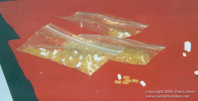
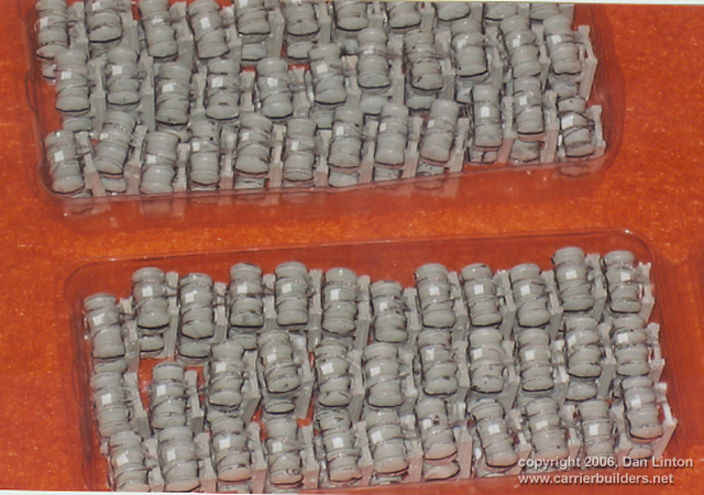
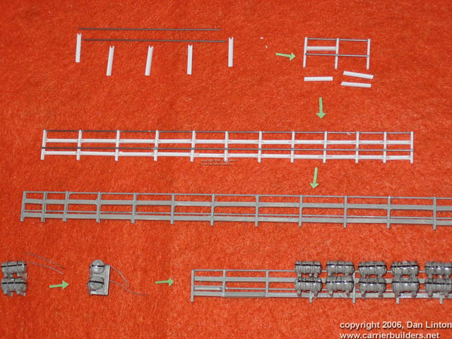
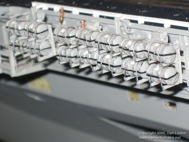
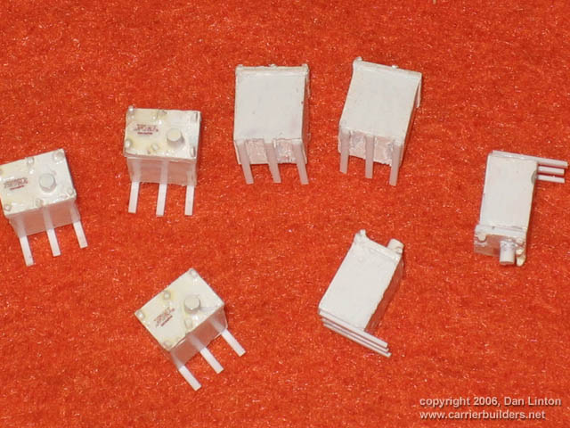
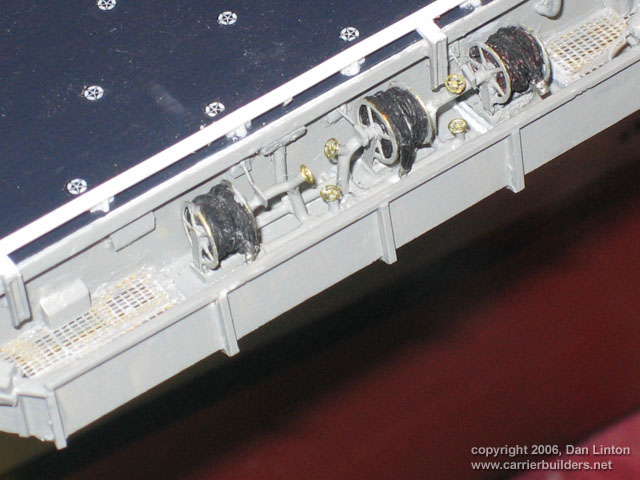
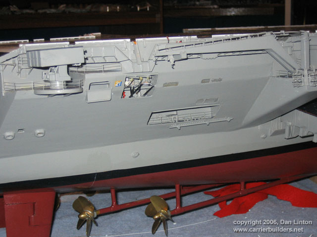
The idea of carving life-raft canisters with any consistency was out of the question. Almost four years ago I contacted Stephane Cochin of Stratosphere Models in Montreal. I provided pictures and dimensions and he experimented and produced 400 canisters for me. In Picture 35 you see these canisters – the white ones were his first run; the semi-clear yellowish resin ones were his finished product. Picture 36 shows a large number of these canisters and supports completed: they are painted and decaled but still need a spray of Dullcote. The construction sequence for the canisters and their supports is seen in Picture 37 and they are usually found in pairs. Each canister has inside a life-raft which inflates once in the water to hold 25 men: there are 242 of these, or 121 pairs, on the Nimitz (242x24=6050). Picture 38 shows the construction sequence for the railings that the canisters hang from and Picture 39 shows some of these railings attached to the catwalks. Picture 40 shows the pyrotechnics(?) boxes during building and then attached to the model (Picture 41). Picture 42 shows the hose reels. Again, there is no PE in 1:144 for these structures. What was used for the fuel reels (top of Picture 42) came from a fret of Aber hand- brakes. These have five spokes and the actual ones on the Nimitz have eight – but this is the best I could do. At the bottom of Picture 42 are the water hose reels, and these I carved out of styrene. Picture 43 shows some of the plumbing for some of the fuel hose reels: I left the small hand valves unpainted so that they would show up better in the picture. Picture 44, starboard stern quadrant complete – but notice the bent railing behind the BPMDS launcher. PE handrails in 1:144 are available but they are really too thin (ideally, the metal would be twice as thick) but because the are so light they can easily be re-bent (as I did after this picture) or replaced. Picture 45 shows the stern: what is missing is a flag to be added later.
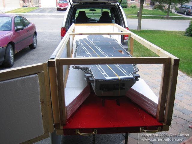
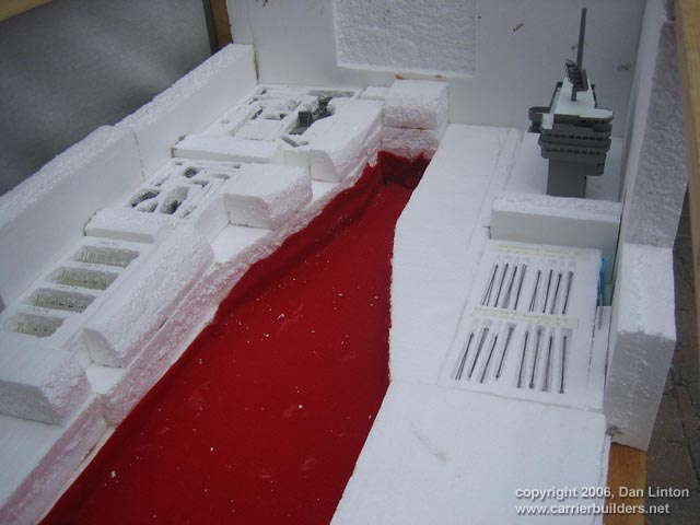
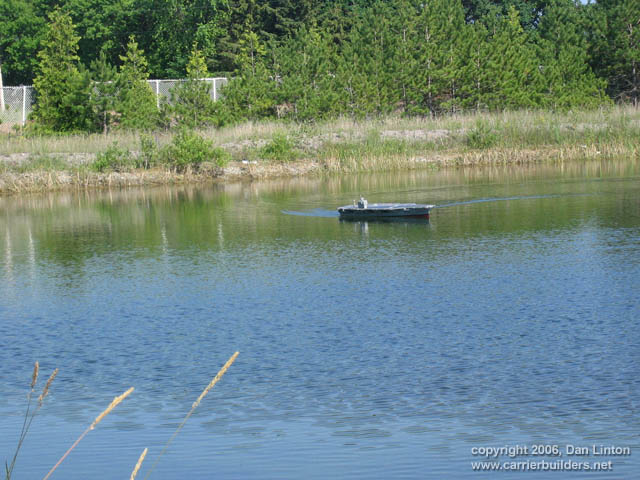
Picture 46 shows why a flag would be a late addition: this is the first time the Nimitz was put in its carrying case and I didn’t know how much room would be left when I closed the door (on the left). Picture 47 shows the case just before the ship was put inside, with various antennas, cables, JBD’s in their styrofoam cut-outs. Picture 48 shows the Nimitz on the water for the first time (June 24, 2006). The bow is too light and more ballast is needed on the port side. But the two radars worked and the ship responded well until the rudder linkage slipped. Then it was tricky trying to get the Nimitz back to shore when it only wanted to turn in one direction (à la Bismarck). The pond belongs to Jeannine Dupuis, my mother-in-law, who also lent me her van. But we have no picture of Jeannine, or any more of the ship, because the batteries on my digital camera decided to give up at about the same time as the Nimitz’ rudder control. And when back on shore I saw a large bulge on the forward flight deck: the plastic was separating from the wood. Being a man and thus not being allowed to cry, I did one thing that most people (and certainly all Canadians) understand – I had a beer. And then another one. And …
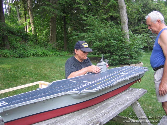
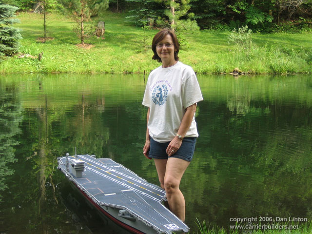
Sunday morning, June 25, I managed to re-glue the forward flight deck, re-connect the rudder linkage, put in ballast as needed, re-glue some broken pieces, and try again. This time it was the pond of a gentleman I have played volleyball with for ten years every Tuesday night, Juris Zivtina. That’s Juris and his wife Ruta leaning on the carrying case, the pond to the right, in Picture 49. Picture 50 shows me setting up the superstructure and radar tower on the Nimitz as it rests on an old picnic table. And on this day the model sailed beautifully (but loudly) for almost two hours. Picture 51 shows it floating at rest: standing beside it is my wife, Susie Dupuis, who is a saint, so vast has her patience been with my obsession these many years. I really don’t have adequate words to express my gratitude.
End of Part VI.
Go to: Photos and text © 2006 by Dan Linton December 15, 2006 |