AircraftProfilePrints.com - Museum Quality Custom Airctaft Profile Prints
The working features on my model of the Charles de Gaulle can be grouped into eight areas : propulsion, the stabilization system, the elevators, the anchors, the island with its radars and lighting, the flight deck lighting, the catapults, and the jet blast deflectors (JBD’s) and their launch cupolas or shelters. The JBD’s and the shelters were described in Part 2; the island with its radars and lighting will be described in Part 4; and the propulsion system will be outlined in the last article, Part 7. What remains then, for this Part 3, is the flight deck lighting, the catapults, the stabilization system, the elevators and the anchors.
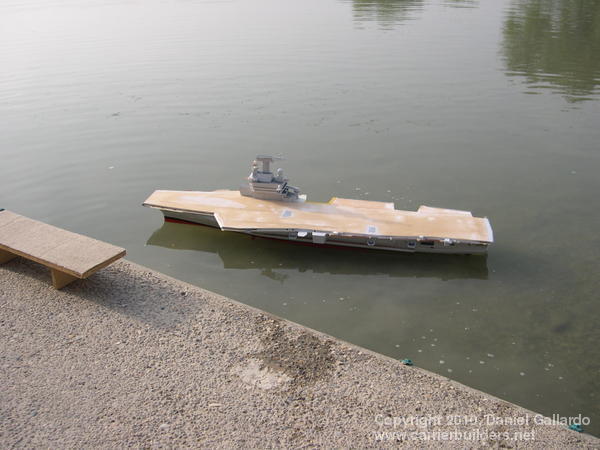
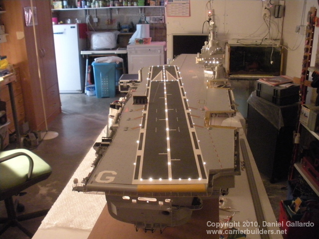
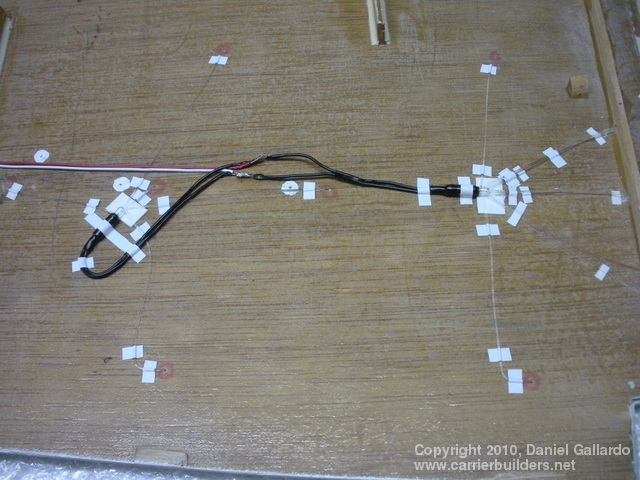
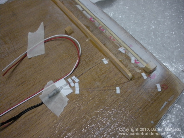
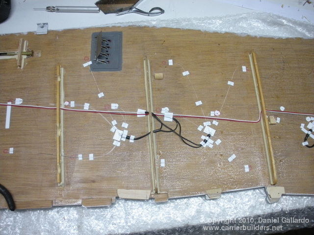
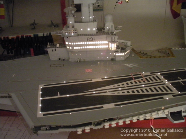
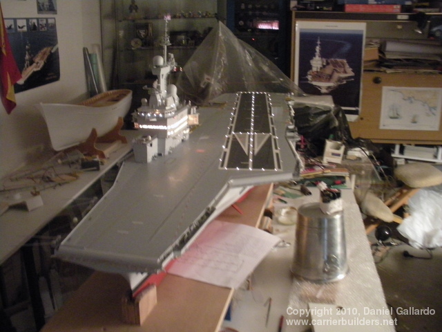
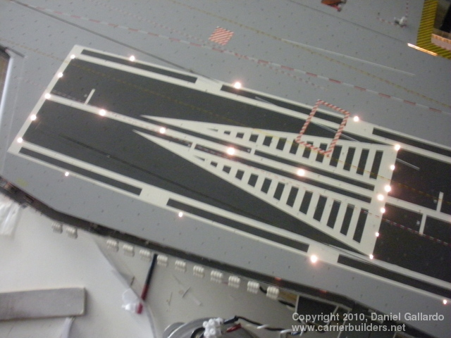
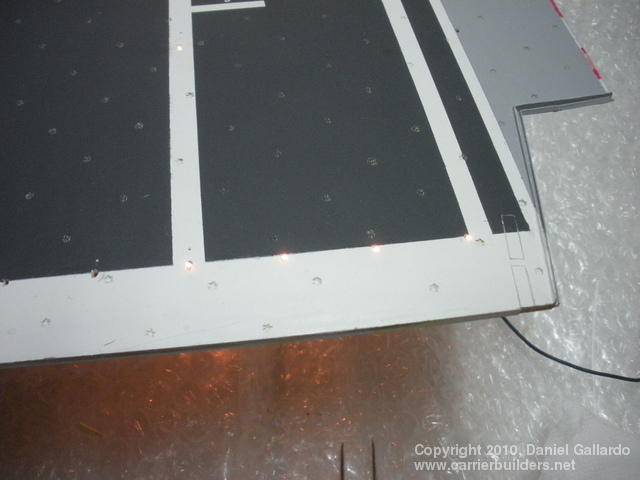
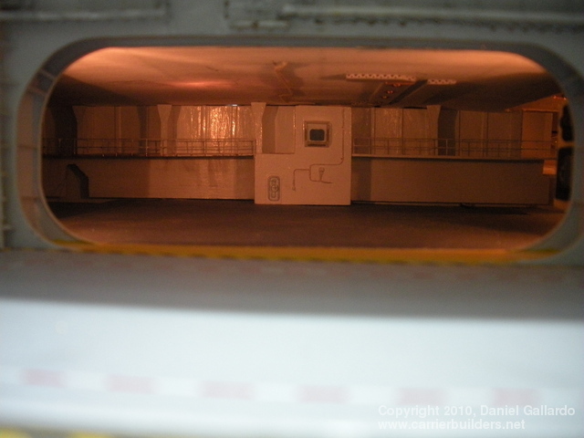
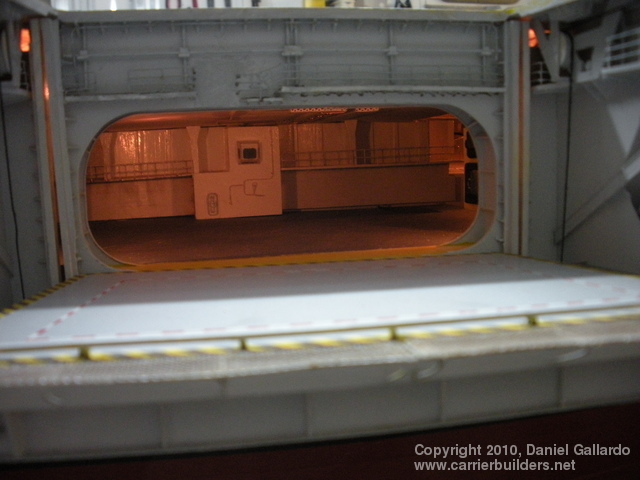
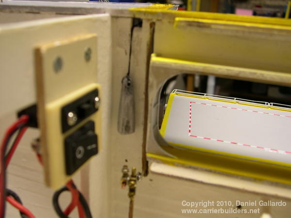
The flight deck lighting, as seen in picture 1 above, was created by using fibre optic lines taped to the underside of the flight deck (picture 2); the fibre optic lines meet up with mini-bulbs taken from a Christmas garland (with my wife’s permission!). The wires from the Christmas lights were soldered to thin plastic wires, the red, white, and black ones seen in picture 3. Picture 4 shows how extensive the taping had to be underneath the flight deck. Pictures 5, 6, and 7 show the lights on the flight deck. Picture 8 shows lights on the flight deck and you can see lights reflected on the plastic sheet the model is resting on. This reflected light comes from the quarter-deck (described in Part 1) which is also lit up –it can be seen in picture 1 above. Pictures 9 and 10 show the hangar deck near the forward elevator. Here the detail is minimal as it is an area of the model that I have not yet finished.
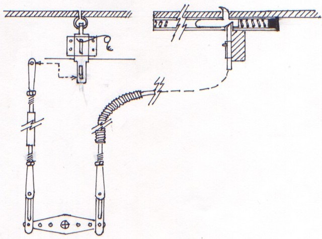
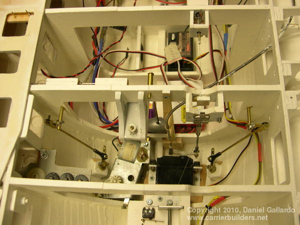
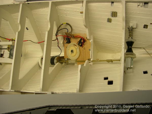
Picture 11 is the diagram showing the action of the catapults. Notice on the right hand side of the diagram that once the servo pulls on the wire, it releases the catapult bar (the small tooth-shaped section above the level of the flight deck) allowing the spring to shoot it forward. It has to be returned manually. A part of the spring mechanism can be seen in picture 12 at the top left-hand corner. Amid all the jumble seen in picture 13, the long, thin tube found in the centre but moving up and to the right holds the wire to activate the aft catapult. Its companion, seen to the right just behind the black box, is connected by a very thin wire to the spring mechanism seen inside the small box to the top right-hand side of the picture, the site of the forward catapult.
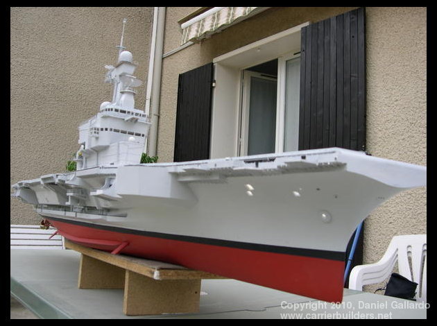
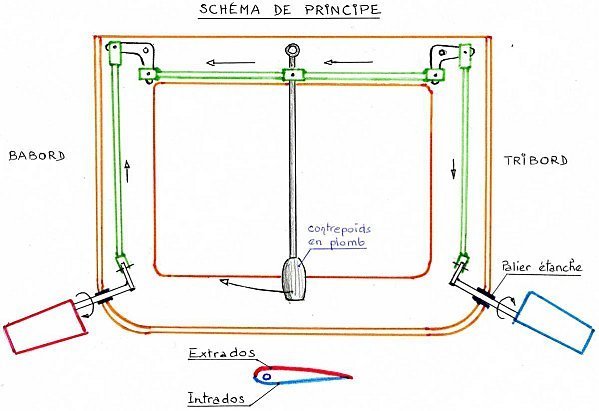
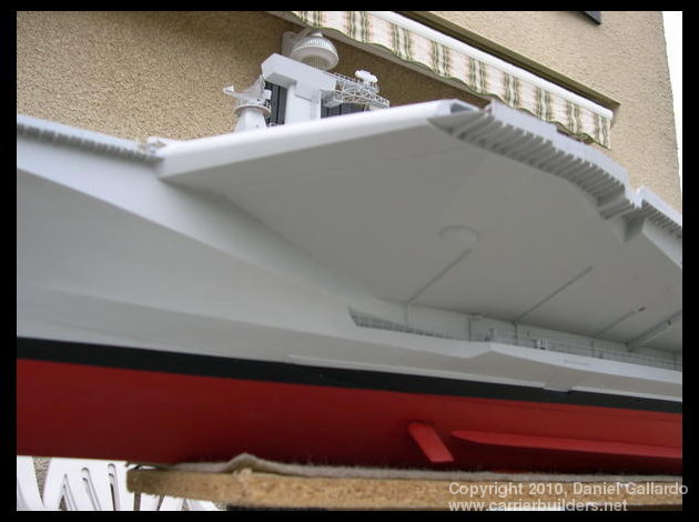
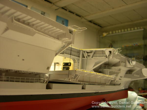
Picture 14 is the diagram used to describe the system used to minimize rolling on my model of the Charles de Gaulle. On the actual ship there is a weight-compensating system that works in conjunction with the stabilizers. As the ship begins to roll or heel to port for example, a 25-ton weight is pulled across, just under the flight deck, by pulleys to counter-balance and dampen the roll. So much of the Charles de Gaulle is made up of structures, such as the islands and various sponsons, that are high above the waterline on a relatively narrow hull that this system had to be installed to dampen oscillations. I have no counter-weight but did install anti-roll stabilizers fore and aft. In the diagram (picture 14) you are looking forward from an aft position. Notice how the stabilizers are shaped very much like ailerons on an aircraft. In this configuration, the vessel will be turning right and the stabilizers are coupled together [Ed. note: couple de redressement=damping couple]to dampen any roll. The following translations will help you to understand the diagram. Babord=port; tribord=starboard; palier=bearing; étanche=watertight; and contrepoids de plomb= lead counterweight. A 60-gram fishing weight suspended from the connecting rods will exert a force when the ship turns and this will be transmitted to the stabilizers which then will work as ailerons to counterbalance the list. Picture 15 (seen at the top of this chapter) shows the stabilizers, one just before the bilge keel and one just aft on the starboard side. Picture 16 (below) shows the forward stabilizer on the port side; and picture 17 shows the stabilizers in place long before the hull was painted.
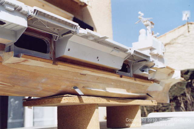
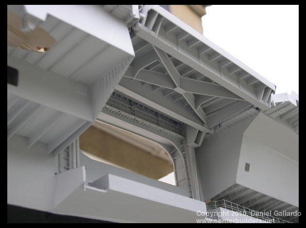
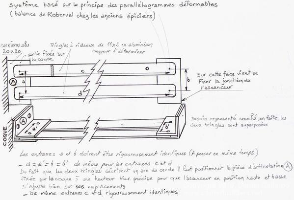
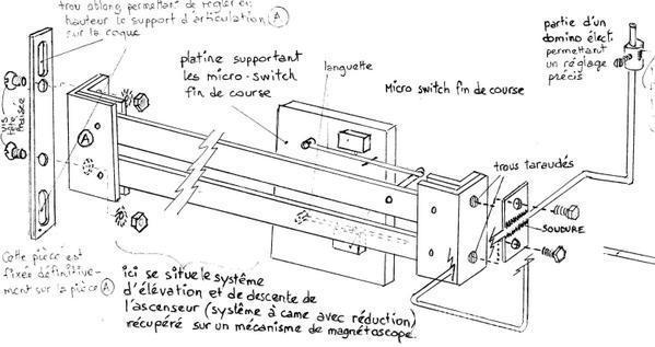
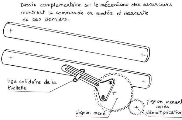
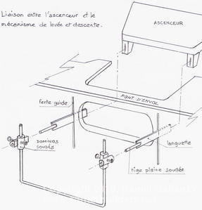
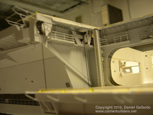
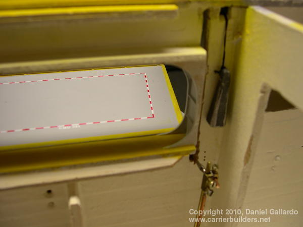
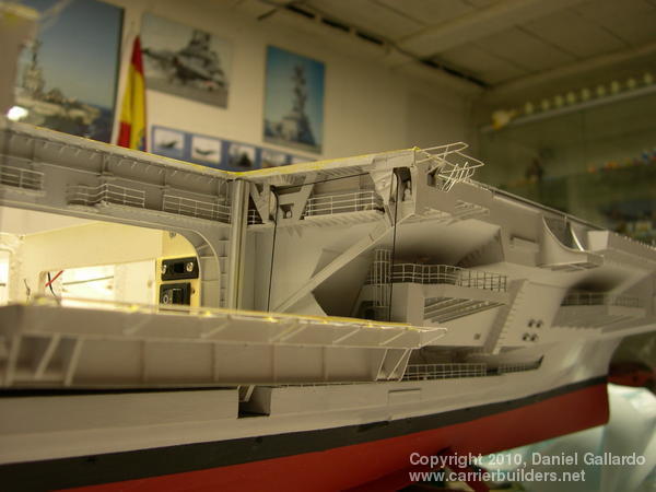
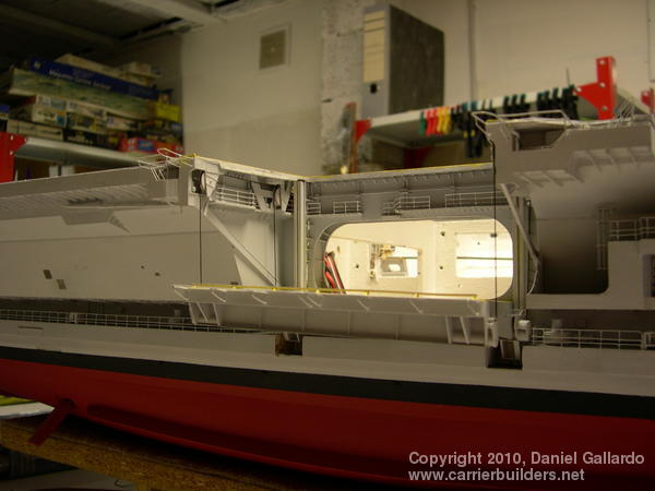
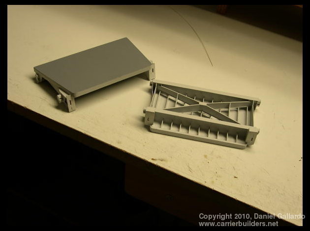
The basic idea for making working elevators comes from the weigh scales used in spice shops, with their two balance beams and pans. The diagram that is picture 18 is the beginning of construction for the working elevators. [Ed. note: canièras=corner irons; tringles à rideaux=curtain rods; a and b must be strictly identical and the holes have to be marked and pierced at the same time] Piece A, two angles one inside the other, has to be joined to the hull at a very precise height so that the elevator can be adjusted for its exact high and low positions. Notice that the bottom half of this diagram has simply been turned 90º. Picture 19 is the second diagram in this series. [Ed. note: at the extreme left it reads: ‘flat-head screws’; top left, ‘oblong holes allow adjustment of the support arm A; ‘palatine’ = support plate for the micro-switch taken from a tape recorder; languette=tongue; at the top right – part of a stopper allowing precise adjustment; trou taraudés = threaded holes; soudure=solder]. Picture 20 is the third diagram, showing the relationship of the cross-bars to an actual lifting mechanism. [Ed. note: ‘tige….’= stub axle; pignon mené = lead gear; pignon menant = reducing gear]. The final diagram, picture 21, shows how the elevator is put in place. The ‘pont d’envol’ is the portion of the flight deck that is permanently in place. The ‘fente guide’ is the guide slit. [Ed.note: ‘tige pleine soudée = solid stem soldered]. All deck-edge elevators on modern carriers are supported with the aid of steel cables. To imitate this I used waxed, black sewing thread. The pulleys had to be deeply grooved to prevent the thread from jumping out (picture 22) and to keep the threat taut I used 10g lead sinkers tied to the ends (pictures 23 and 24). Picture 25 shows the forward elevator and picture 26 the rear elevator. Notice that there are two cable lines on each side of an elevator (picture 27). The final picture (picture 28) shows the two elevators at an early state in their construction. To see the elevators in action you can go to: http://www.dailymotion.com/video/x33ag6 dscn3788 blog http://www.dailymotion.com/video/x33auh dscn3789 blog http://www.dailymotion.com/video/x33ax5 dscn3784 blog http://www.dailymotion.com/video/x33azu dscn3787 blog Please forgive the fact that these are not as clear as they should be. Each one only takes 8-9 seconds
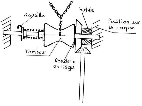
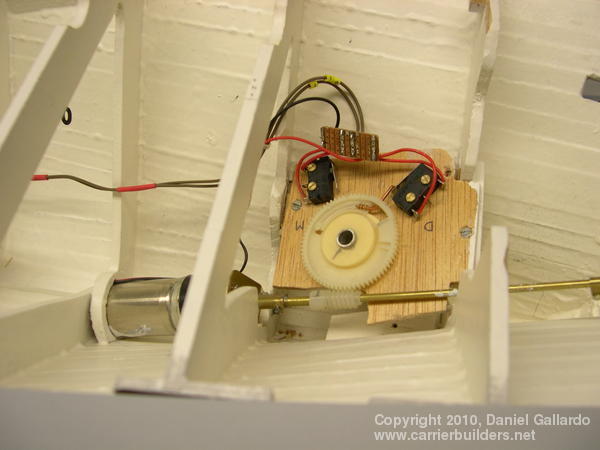
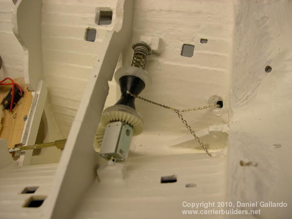
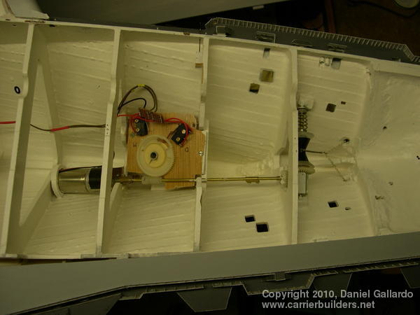
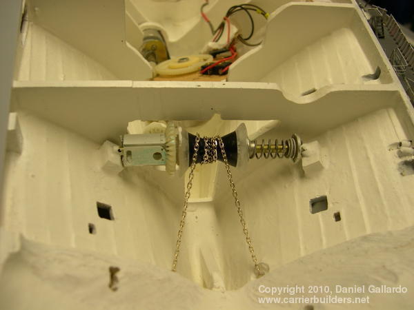
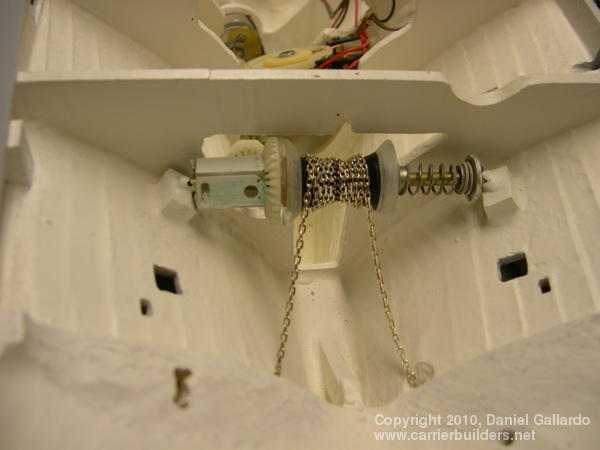
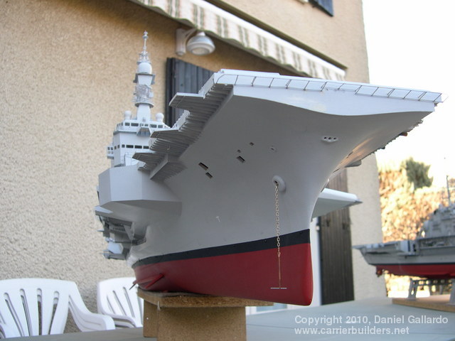
Once again there is a diagram (picture 29) showing how the anchors can be raised and lowered. [Ed. note: from the left--- goupille=pin; tambour=drum or spool; rondelle en liege =cork buffer; butée=stop; fixation sur la coque= glued to the hull] In the diagram , the dots represent a spring seen from the side. Picture 30 shows how the motor is as low as possible in the hull. A wormscrew puts into action a cogwheel: note the connection mode by the copper wire – as the cogwheel turns the wire will travel to the left in an arc until it touches the next micro-switch contact point which will cut off the movement (letting the anchors out). A radio-control command reverses the process and the anchors are raised. The next picture (picture 31) shows both the spring and the full extension of the chain. The entire set-up is seen in pictures 32 and 33. Picture 34 shows the anchor chains wrapping around the spool without fouling each other, and picture 35 shows the chains fully raised. The final picture (picture 36) shows a length of chain being used as a test – it is not the full length nor is it painted. Next: Part 4 – the Superstructure, its Radars and Lighting
Photos and text © 2010 by Daniel Gallardo June 9, 2010 |