Because of the amount of materials I’m hoping to cover, I will have to divide this article up into several parts. I’ve been thinking about doing just a simple write-up and skip over most of the details. However I’ve settled upon a more complete article that covers as I may the works I’ve done and the reasoning behind them. I hope this will eventually be helpful to those who may also want to approach the Revell F/A-18E in like manners.
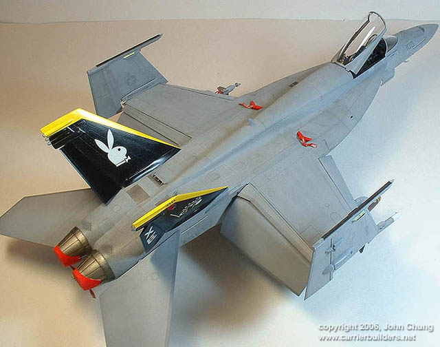
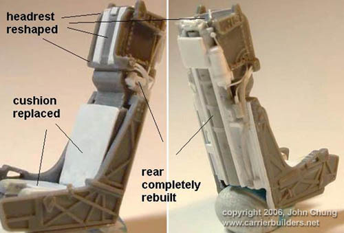
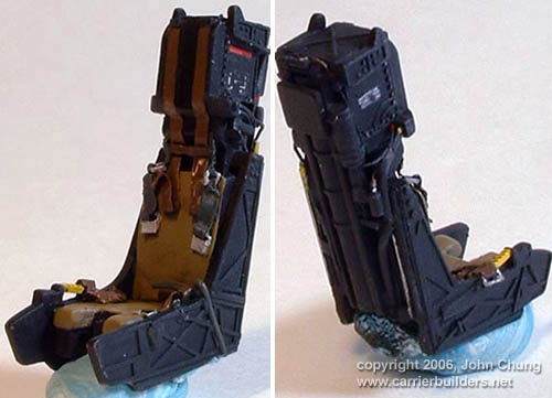
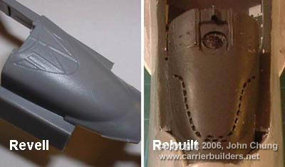
Revell included a decent rendition of the SJU-17 NACES ejection seat, and was a natural starting point for detailing. The over-simplified aft section was removed and rebuilt with correct width and details. The headrest should be recessed between the hardness instead of protruded and was corrected. Further improvements included seat cushion modifications, scratch built harness and ejection handle.
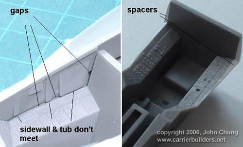
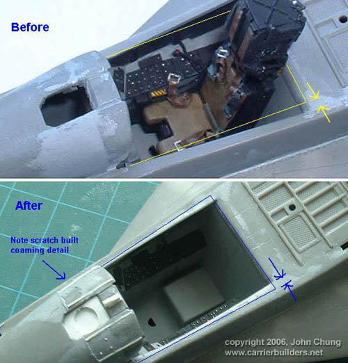
The main instrument panel was an absolute gem out of the box and the control stick wasn’t bad either, tho the throttle was rebuilt from sprue. I did notice the cockpit side consoles and sidewalls didn’t meet up, and a couple evergreen strips were used to remedy the issue.
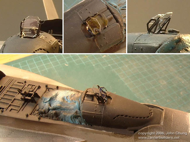
The instrument coaming did not represent those on the Super Hornet, so it was slightly reshaped and modified with sheet plastic and stretched sprue. De-fog vents were made by grooving the plastic and filling it with putty then immediately impressing the holes before the filler cures. This useful trick was outlined by master pattern maker Jef Verswyvel on his tutorial for the 1/32 F-16C cockpit. A scratch built HUD was made from styrene strips and acetate sheets.
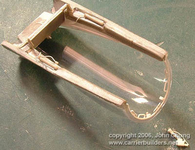
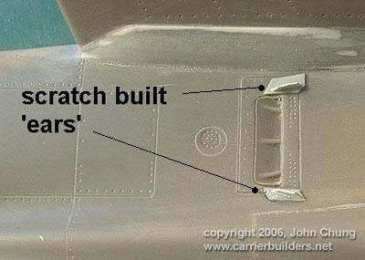
The aft decking was modified by relocating the canopy hook holes and opening a couple recesses that weren’t present. Eyehooks were also added along with a scratch built canopy actuating mechanism as the kit example was poorly represented and undersize. Note that the width of cockpit sill was modified as well according to references.
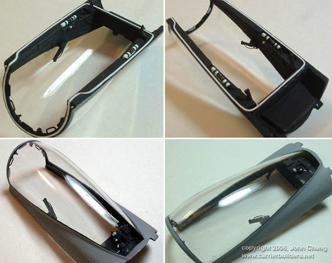
I’ve found the provided canopy interior framing to be too narrow in height, evidently a byproduct of the misshaped canopy/spine contour (more on that later). The framing was thus slightly modified and various scratch built paraphernalia attached prior to painting. Thin electrical tape strip was used to represent the canopy pressure seal, a trick from Bernhard Schrock’s Hyperscale F/A-18A article.
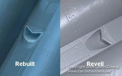
The main fuselage was done in an upper-lower halves setup, including the wings inboard of folding mechanism. A few pieces needed installation prior to fuselage closing, which fit generally well. Revell recommended installing the intake/side fuse pieces prior to closing fuselage halves, tho I’ve elected otherwise to facilitate a stronger joint and easier clean up of filler, as both the lower LEX and aft fuselage needed a bit. Before the fuselage halves were closed the APU exhaust on the bottom was drilled out and rebuilt.
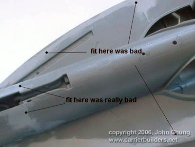
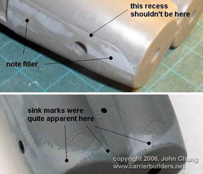
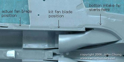
As the Revell supplied intakes were about half the lengths as they should be, I’ve elected to install intake covers instead. Personally I would have preferred the appearance the full trunks instead. Particular attention was needed near at the rear fuselage where much filler was needed, mostly due to plastic shrinkage. There was also step in the plastic just below the horizontal stabs that shouldn’t exist and needed addressing. Vortex generators were added on either sides of the heat exchanger exhaust located between the vertical stabs. The exchanger exhaust themselves are passable, but I’d rebuild them if I were to do it again.
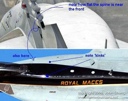
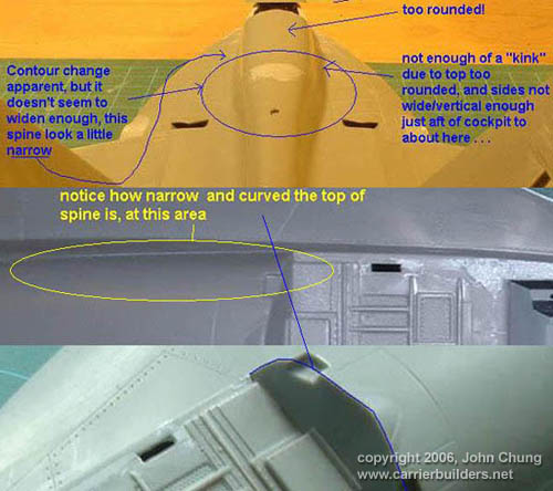
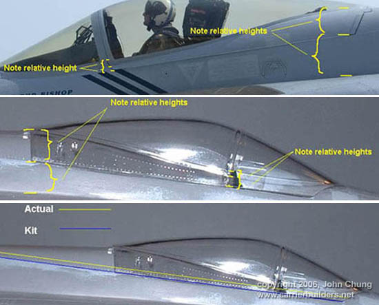
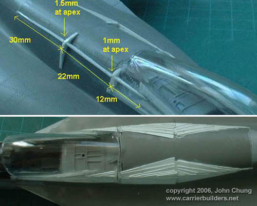
It came to my attention that the Revell spine was somewhat off in its contour, and that a total fix would be rather difficult if not impossible. However, it’s possible to get it to look relatively right. The issue is confined to the immediate area just aft of the cockpit, which is too narrow and may be a little too tall. This resulted in a spine cross section that’s too rounded compared to reference images. The shape issue in term propagated over the entire cockpit length and affected everything up to and including the forward windscreen. The main canopy framing was such that its overall width and height became too small great, respectively.
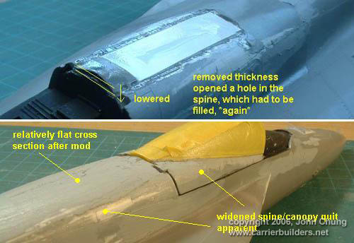
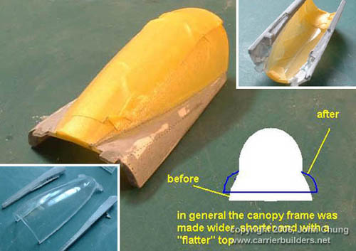
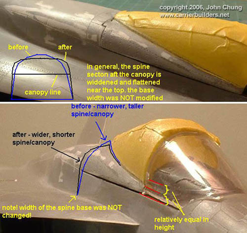
I eventually lowered the spine and widened it along with a section of the cockpit for a more representative cross-section. The canopy frame was judiciously removed from the clear section, modified and then reattached. The forward windscreen was also lowered near the back to reduce its slope and produce a better looking frame height. The overall fix seemed dramatic over a few attempts, but it’s relatively straight forward now that I know what I needed to do. Although not completely accurate, it does produce a more accurate looking spine.
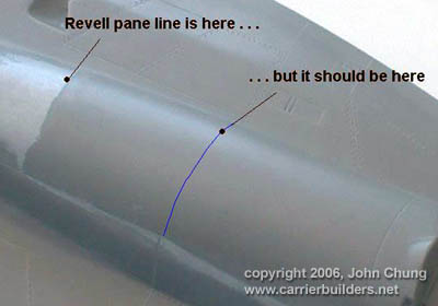
Finally, the panel line on the spine insert was misplaced and was rescribed to the correct location.
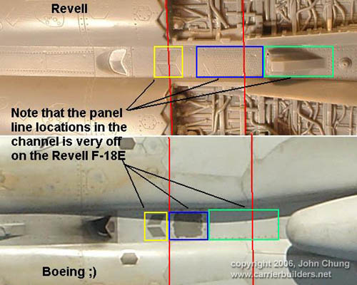
As a last note, I was pointed out that the ventral fuselage channel between the engines is too deep, and careful examination revealed this to be correct. However, addressing this issue would encounter too many constraints and considering the panel line details are also quite off, it would render it too much work for to little benefit. I chose to neglect this issue.
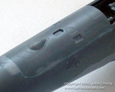
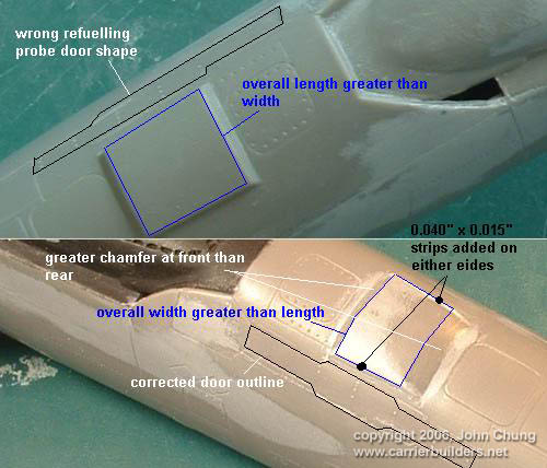
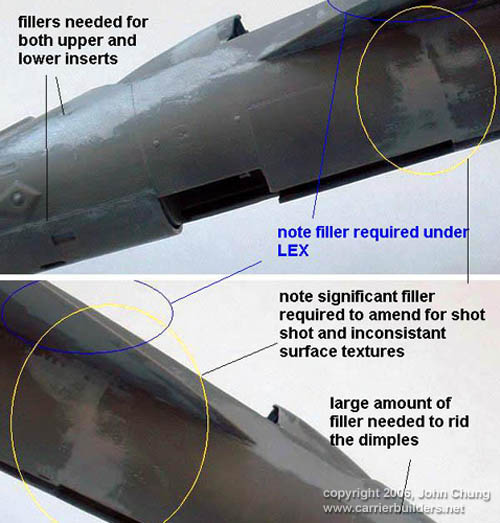
The forward fuselage is a four-piece affair comprising main left-right sections and top and bottom inserts. The two inserts needed careful cleaning before attaching and still a little filler to smooth out. Both the IFF box and refueling probe doors were slightly misshapen and were fixed accordingly without too much fuss.
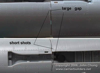
Overall fit of the forward fuselage assembly was not great and my copy also showed distinct evidences of short-shot around the joint. The avionics bay hinges represented by raised steps also caused issues as lost details were near impossible to replace.
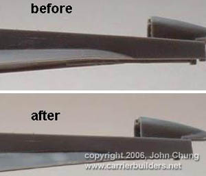
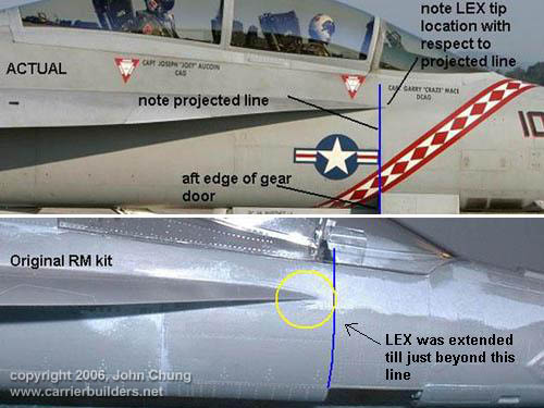
Revell mysteriously molded dimples on the forward fuselage just fore of the LEX leading edge that was filled and detail replaced. The LEX tip had a distinctive downward kink and was also a bit short, so it was straightened and extended.
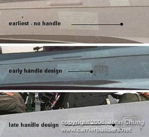
A side note, tho Revell did not include it there should be an entry handle just under the canopy. The earliest aircrafts had no handles, including ‘Vampire 100’. The first handles were a rectangular design and the current batches all have semi-octagonal ones. If you so desire make sure you research the specific a/c for handle configuration.
END OF PART I. Photos © 2006 by John Chung June 22, 2006 |