|
Nimitz-class
aircraft carriers are 90,000 tons of United States diplomacy. Throughout
recent history, the appearance of a US carrier, always ready on arrival,
has often been enough to diffuse an international incident.
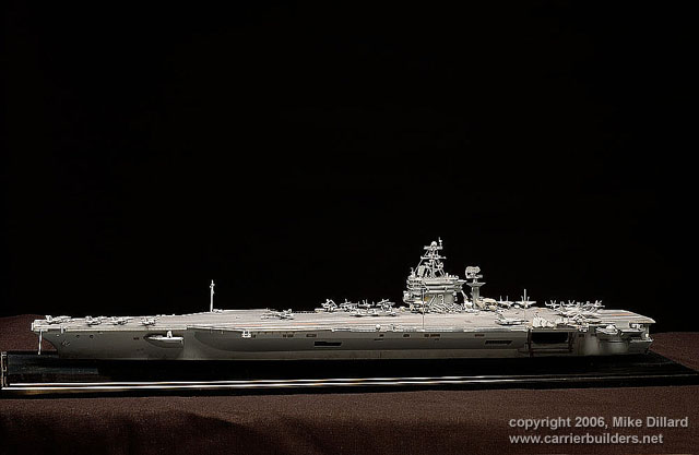
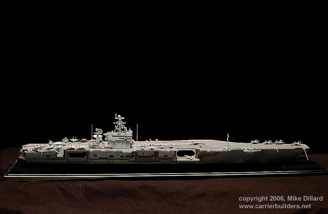
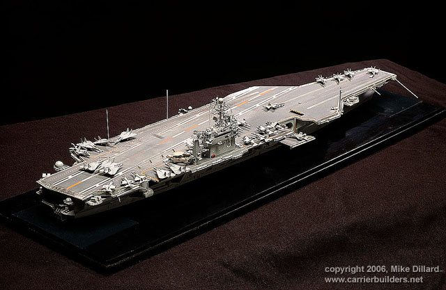
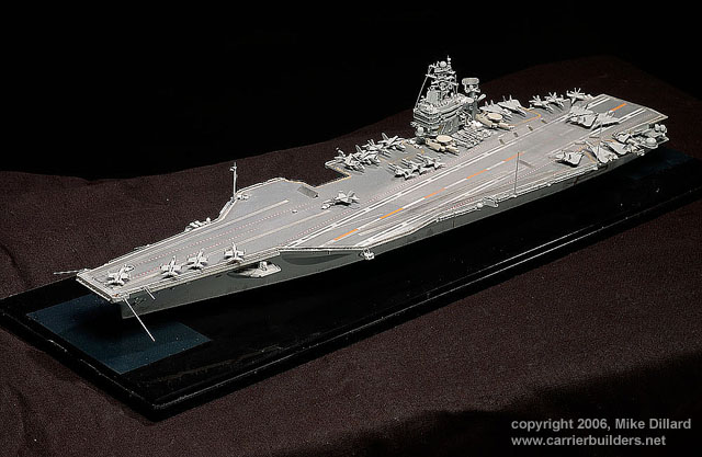
My latest project has been an endeavor to convert an Italeri 1/720th
scale Nimitz-class kit to represent the USS George Washington, CVN 73
and the ship’s 2004 deployment. My two previous projects, after a near
two decade lapse in model building, were WW2 1/700th scale waterline US
Navy carriers. I was ready to tackle the big ship, on the small scale.
The George Washington is the sixth Nimitz-class ship and was built for
the US Navy by Newport News Shipbuilding, (now Northrop Grumman Newport
News,) and was commissioned in July 4, 1992.
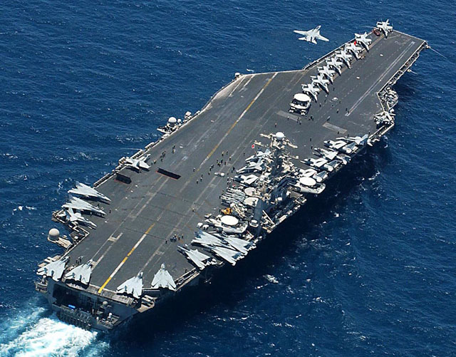
Research photos, of the ship during the 2004 deployment were easily
obtained from the US Navy Visual News Service’s excellent web site, Navy
Newsstand at www.news.navy.mil.
Since there isn’t a kit of the “GW” I chose the USS Theodore Roosevelt
CVN 71 kit for the project. This kit was advertised to contain ÒnewÓ
aircraft. I quickly realized that the kit airplanes, while new, would
not be adequate, so I picked up some Fujimi and Pit Road/Skywave modern
US Navy aircraft kits. I ordered Gold Medal Models modern carrier photo
etch set and dove right in.
I removed the lower hull section, of the new kit, to maintain continuity
with my waterline WW2 carriers. I decided to open all the hanger bay and
sponson areas on the kit and put in a simple hanger deck, with no
bulkheads, etc., just to show a plane, or two, through the now open
elevator areas. I put some sections of sheet plastic inside the hull to
serve and then used some sheet to provide a backing to the cut out
starboard sponson areas, so the light from the hanger openings wouldn’t
shine through where it wasn’t supposed to.
I kicked around the idea of drilling out the flight deck pad-eyes since
they flight deck tie downs are visible in this scale. While using my
Dremel would make the chore rather simple, if time consuming, I decided
to follow the LWEA, (Leave Well Enough Alone,) principle. I wasn’t sure
I could maintain a good spacing and lineup of the holes, so instead of
drilling myself into a corner, I exercised a better part of valor.
One of the things I’ve noticed from many different modelers, is that
they often get modern carrier flight decks all wrong. They may do a good
job weathering the deck stripes, etc., but all too often the represent
the flight deck as a single color! The nonskid surface applied to modern
carrier decks is never put on over the entire deck at one time. This
relatively black surface fades very quickly in sunlight and so the deck
will consist of several different shades of gray often with well defined
sharp edges between lighter and darker areas. Even a new carrier, or one
fresh from a refit, with freshly painted deck stripes, will have
different shaded blocks of nonskid on the deck. Reference photos will
bear this out.
I airbrushed
the deck with an original coat of Model Master Acryl Gunship Gray,
#4752, mixed with some light gray for scale effect. Model Master Acryl
offers a Flightdeck Gray, #4234, and I tested that color. Other
modelers, working in different scales, etc., may want to test it too,
but I found it looked too blue for me. After the darker coat dried I
masked a large rectangular area of the deck’s aircraft landing area
following some reference photos, and with a lighter mix of the gray
paints, airbrushed that section. I repeated the process on a couple of
smaller areas. I gloss coated the deck and applied the kit decals,
modified to the match photos, I’d chosen. Since there was no kit decals
for the bow “73” I took a black set of numbers from a spares box. Using
some white stripe decals, I outlined the black numbers on the deck. The
numbers were too short and too wide, but were better than the oversized
kit decals, which I couldn’t have used anyway. Weathering the black
numbers helped to bring the black color closer to the deck’s gray. It
was a compromise. The landing area centerline stripes are too orange,
but with the amount of weathering I planned to apply, I stuck with the
kit stripes. I dull coated the deck and then using washes and dry
brushing with, different shades of Gunship Gray again, I blended the
colors and weathered the deck in an attempt to come close to the photos.
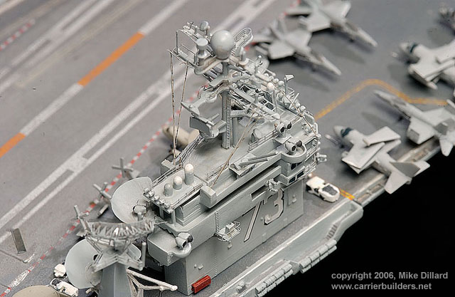
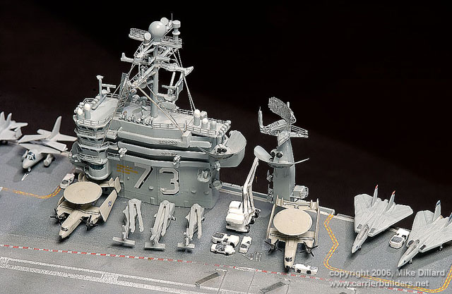
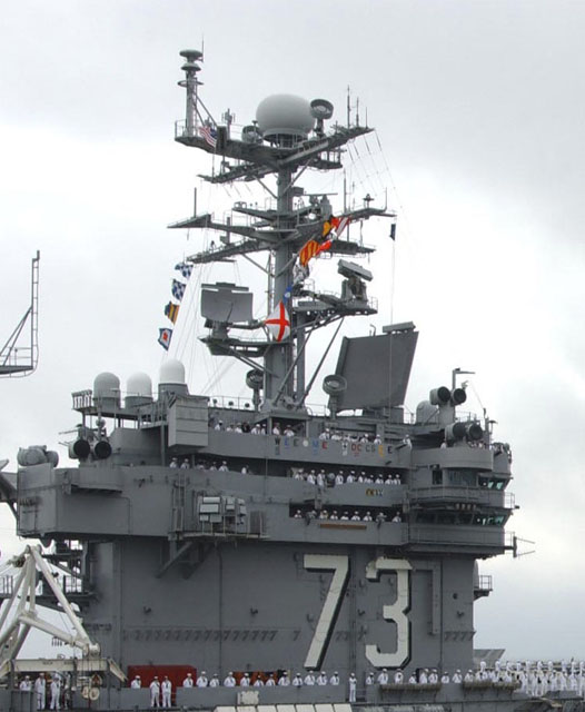
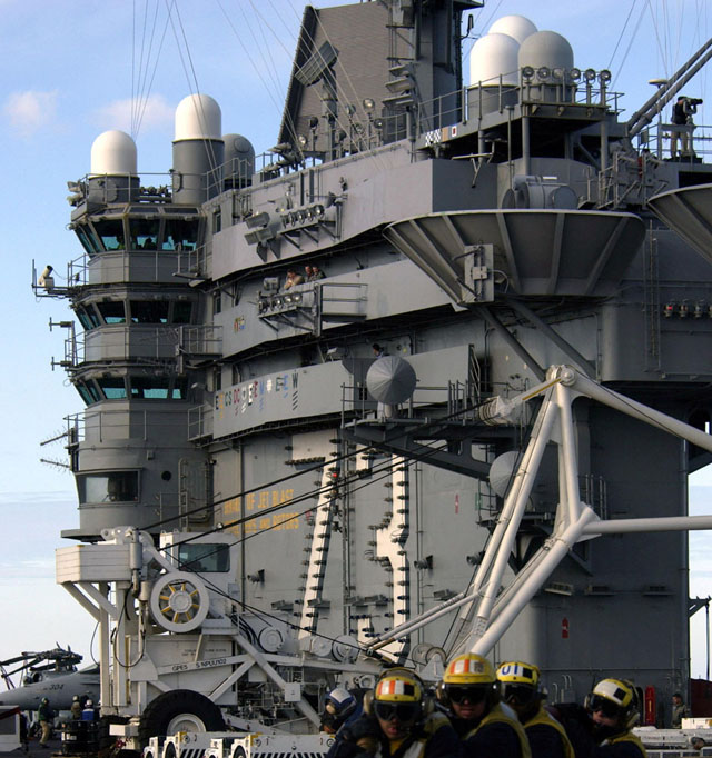
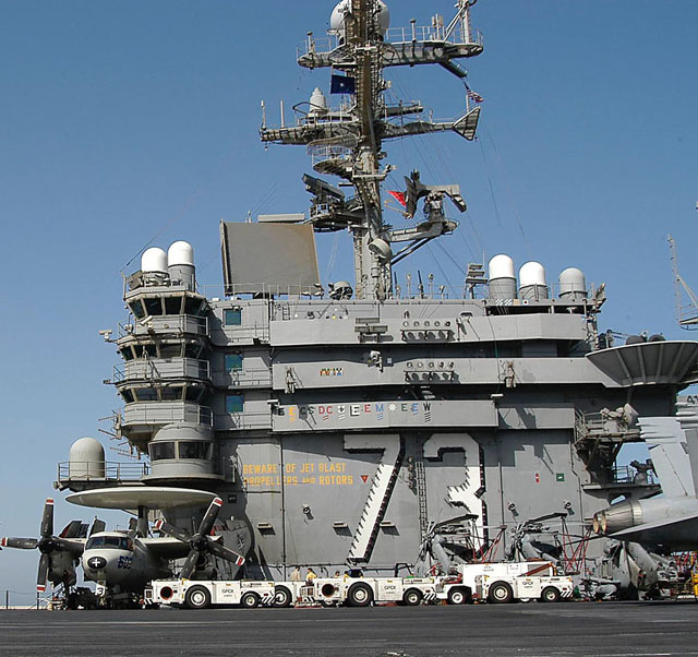
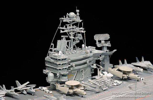
The Washington’s island is different from the generic Nimitz island
supplied in the kit. Using the good Navy reference photos, I did some
simple scratch building for the needed changes to the kit’s island.
Using some sheet and rod, I extended the needed areas on the aft island
and altered the port and starboard sides. I added a few pieces for
antenna platforms and used rounded off rod pieces for additional antenna
domes forward and aft. I added a simple platform low on the forward side
and using a small diameter pencil eraser I created the domed antenna
there. I rounded the eraser off by rubbing it on paper, then soaked it
in Future floor wax, for several hours so the paint could adhere. Once
the GMM railings were added, I counted over 120 parts on the island
alone. I combined some black and white “73” decals for the island
numbers. Most US Navy carriers have the black “shadow numbers” on their
islands, not just stand alone white numbers. Again the decals weren’t
entirely accurate, but a compromise was required.
( A hint here to decal manufacturers: You make good stuff for the
1/350th scale carrier builder. Please don’t forget the small scale folks
too.)
I ended up buying two more Italeri kits during the model construction. I
used a few parts from the John C. Stennis #524 kit and a few domes from
the Ronald Reagan kit #5533. This saved me from having to scratch build
a couple of weapons sponsons, some antenna domes and extra platforms on
the main mast. Later, I still have a post-refueling Nimitz carrier as a
future project by bashing these two kits.
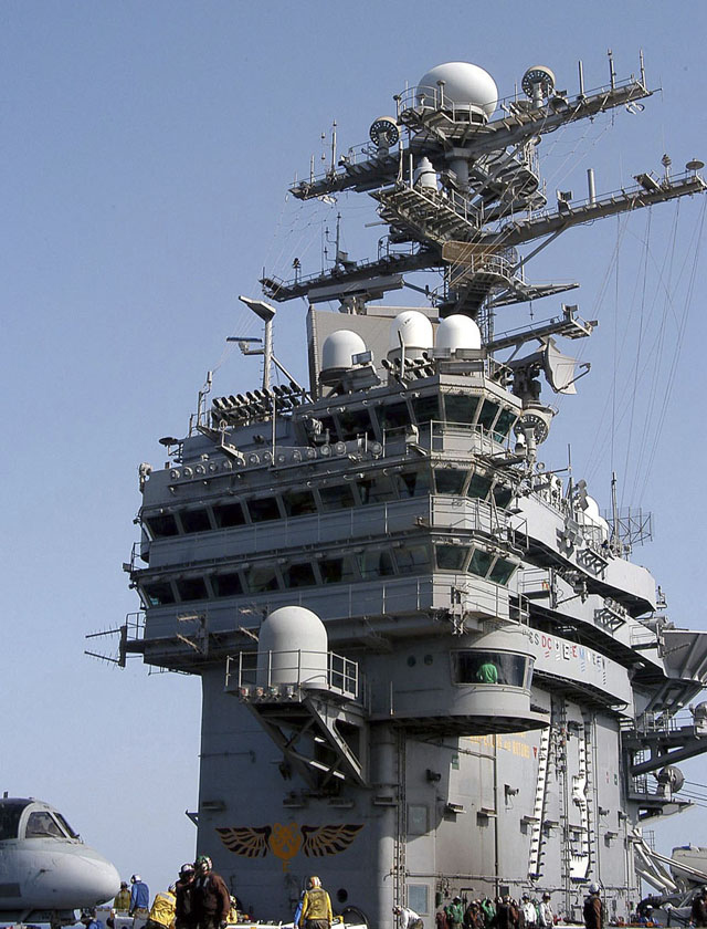
The main mast required a few scratch built antenna parts, pieces taken
from the Stennis kit, GMM photo etched railings and antenna pieces. I
added a few antenna poles cut from a roll of beading wire. The Navy
photos again were invaluable showing the extra pieces required and the
separate additional mast support on the port forward side of the mast.
|
Click on the images to
enlarge! |
I added only
a couple of details to the radar tower built from the GMM fret.
I chose not to use the PE safety nets around the hull, again going with
the LWEA principle. I cut the molded nets from extra flight deck
elevators in the Stennis kit and added them to the bow and around the
CIWS sponsons where required. I believe their use works, in this scale,
and they do match the rest of the nets on the hull. I added the PE
railings as needed. I scratchbuilt two other antenna sponsons, one on
the fantail and the other on the port side aft, guided by reference
photos, and used pencil erasers again for the antenna domes.
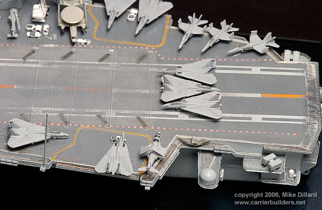
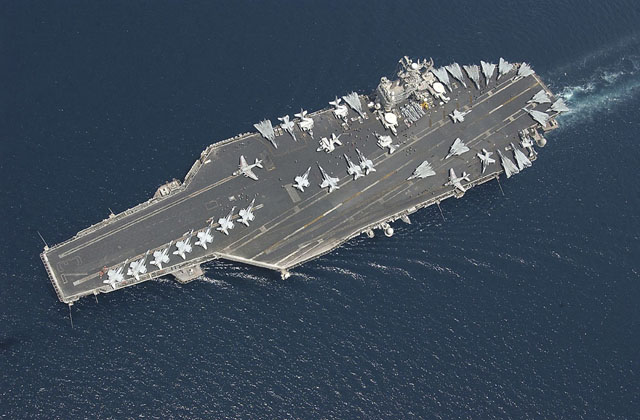
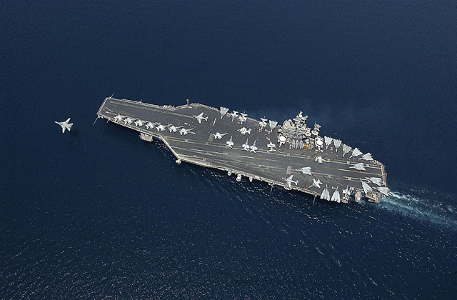
My past carrier kits included only 10-12 aircraft on the flight deck,
but using that few on a Nimitz-class ship made the deck look too bare. I
chose not to make an exact duplication of the aircraft placement from a
single 2004 GW cruise photo, but did spot the aircraft using several
other photos as a reference. Since decals for the correct CVW 7
squadrons were not available in the numbers and varieties I needed, I
used only a few numbers, etc., from the Fujimi and Pit Road/Skywave
sheets. It is indeed a testament to a modeler’s skill to apply all the
small decals to a 1/700 scale aircraft. But to use aircraft types and
squadron markings from planes that never served aboard a particular
carrier, in my opinion, is an incorrect thing to do. Since there are
never more than 12 US Navy super carriers in service, I believe that is
too few a number, to not pay close attention to such details. To build
an Atlantic Fleet ship model and then display it with Pacific Fleet
aircraft markings, when your project is an attempt to represent the ship
at a definite point in its life, doesn’t make much sense. I used a few
lines of color, on the F-14 Tomcat tails to represent the VF-11 Red
Rippers and VF-143 Pukin’ Dogs. I didn’t apply lots of the low
visibility decals to the various aircraft and that is apparent in the
close-up photos. Once the model is mounted in a case and is viewed from
a normal viewing distance, the markings would be almost invisible. This
approach would certainly be incorrect modeling a high visibility
1960s-70s marked air wing though, since all the colorful markings would
be visible at scale.
Oops and goofs plagued the model at final assembly.
I’d mounted my first two carriers flat on the base of the display case,
without any modeled surf, etc., and wanted to do the same thing this
time. When I went to mount the model on the base I discovered the model
had bowed. The bow and stern were lower than the model amidships. The
curve was slight, but mounting it was a challenge. I’ve since read that
this isn’t uncommon with this kit. With my WW2 carriers, I used the kit
box and rolled tape to support the model once the major assemblies were
joined, so I did the same thing this time. I don’t know if this wasn’t
enough support with the much longer modern hull, or the lack of a
ballast bar that is included with Hasegawa or Tamiya kits I’d finished
previously allowed the hull to curve. Perhaps, I caused the bowing by
adding the small sections of hanger deck inside the hull. Anyway, the
model had a bow in it. I drilled holes in the case bottom and very
gingerly with a pin vise drilled matching holes in the base plate of the
model. I passed tube through the base and into the hull plate and
secured the model into place without any damage to the masts or antenna
posts.
My past two models were rigged with human hair and I wanted to go with
it again. It was not to be. My clumsiness in the attempt snapped the
main mast and the radar antenna from the after mast in one slip of a
knot.
I know every modeler has faced situations like this. I recommend heavy
breathing exercises to regain one’s composure. I mounted the mainmast
back into position with super glue, and remounted the antenna. The
mainmast went on fine, but wouldn’t support any rigging tension. I used
some stretched sprue and simulated a few rigging lines. The antenna was
a different problem. I could remount it, but I was afraid to rebuild the
PE part. So, it sits too short on the top of the tower. I will have to
replace it by ordering another GMM fret and rebuilding the whole piece.
I mounted the aircraft to the deck with white glue and figured the model
was complete. The modeling fates, though still had one trick left to
play on me.
I took the model to the studio for the photo session. I’d done this with
previous models without incident. I setup the background and strobes and
began the shoot. Things went well until I went to do the close-up series
on the aft flight deck. I noticed one of the F-14s on the number 4
elevator had its nose pointing skyward. The white glue joint on the nose
gear had let go. I must have jarred it loose turning the model for the
various angles during the shoot, I thought. Since I had no glue with me,
(note to self: remember to bring white glue to studio next time,) I
gently removed the plane from the deck and continued to finish the
shoot. I didn’t have time to review all the shots on the digital
camera’s LCD screen, nor to give them much of a look with a studio
computer, so finished up and headed home. Then I noticed that the
Tomcat’s nose was pointed skyward in ALL my overall shots of the model!
(Did you catch it on your first look?)
Oh well... Lessons learned.
Building a good representative model of a specific carrier from the
Italeri kits isn’t hard at all. With the wonderful help from readily
available, up to date photos, it makes an excellent ship project.
Photos © 2006 by
Mike Dillard
March 21, 2006
www.carrierbuilders.net |