|
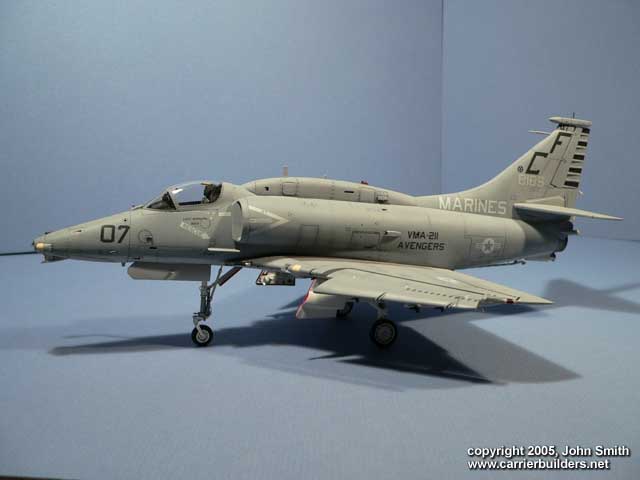
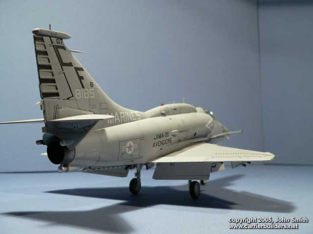
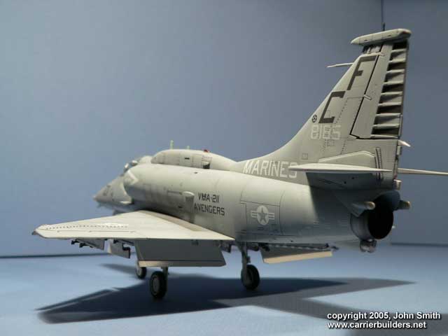
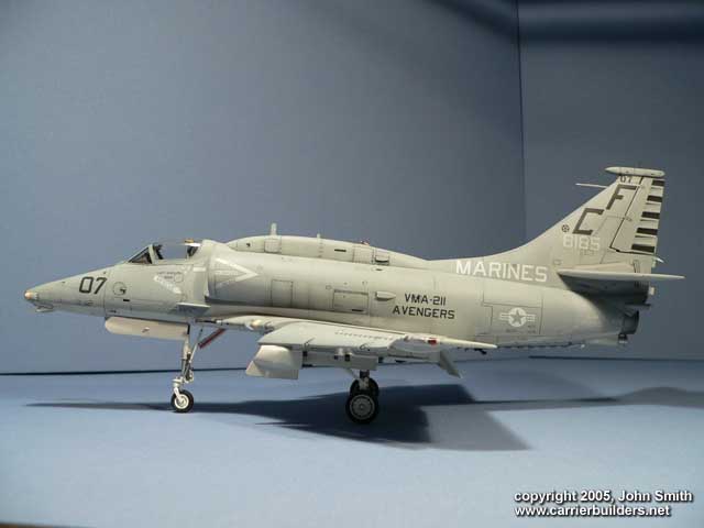
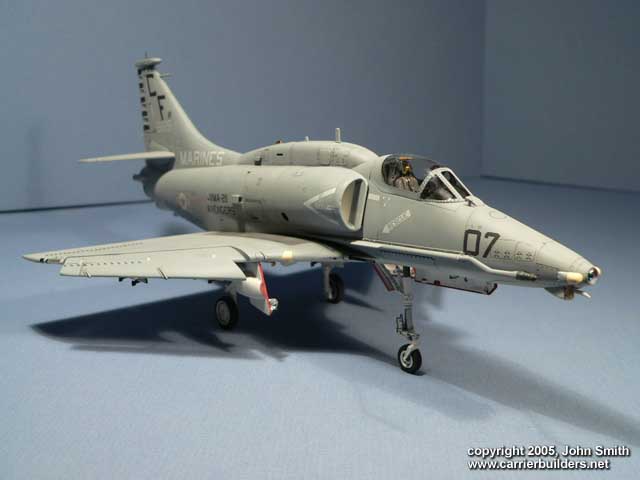
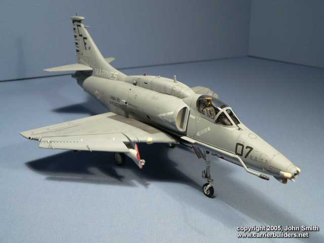
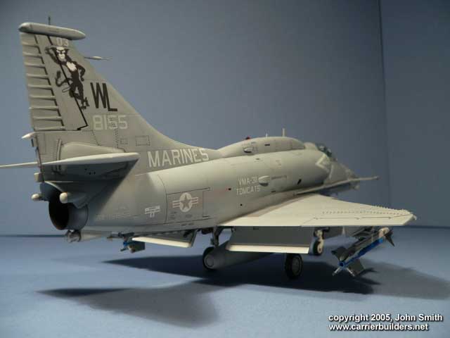
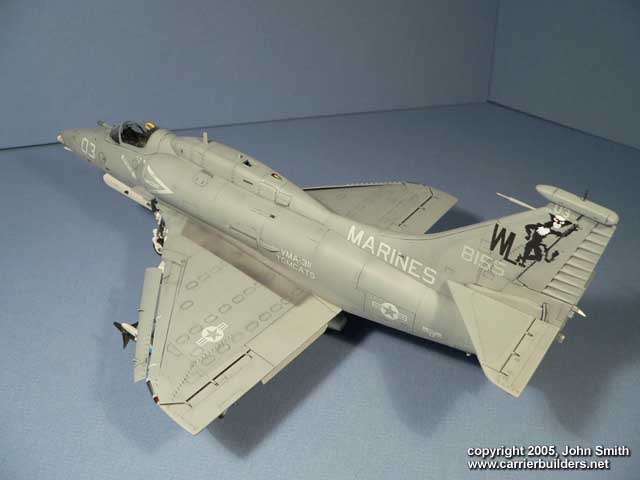
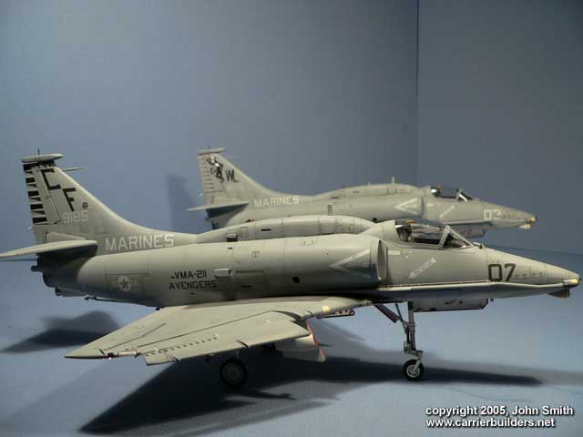
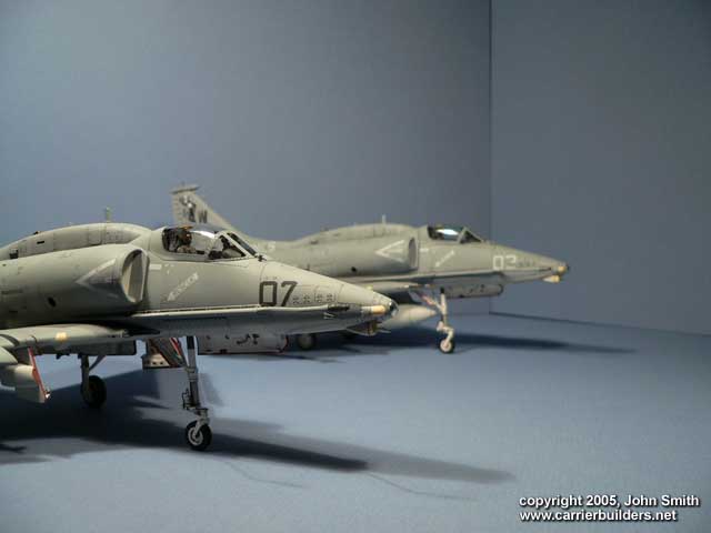
Kits: Hasegawa 1/48 PT33(07233)
Decals:
-
Two Bobs 48-092 Low-Vis “MIKES” part 1:
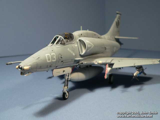
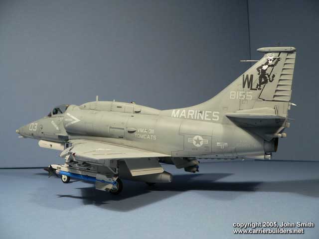
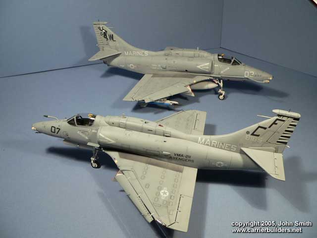
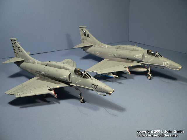
VMA-311 option used
-
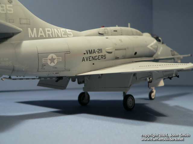
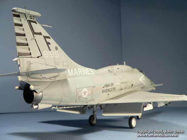
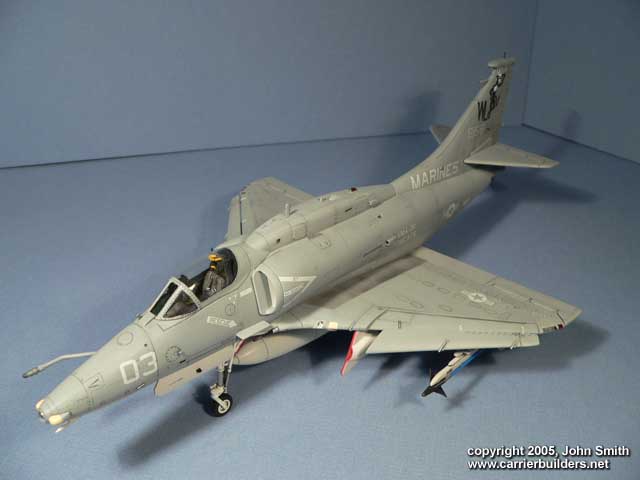
Two Bobs 48-093 : Low-Vis “MIKES”
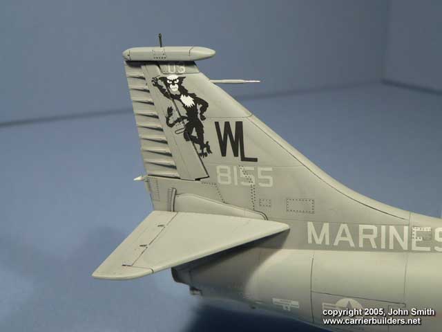
part2:VMA-211 option used
-
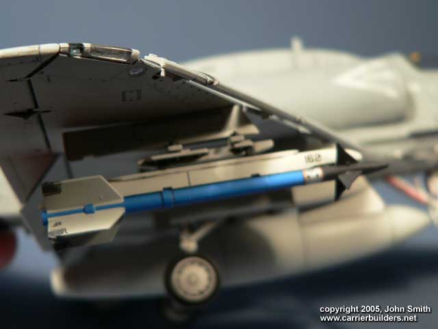
Two Bobs 48-086: U.S. Air to Air Markings:
used on sidewinders for VMA-311
Enough is known that the A-4 series by
Hasegawa builds straight from the box quite well. Building these two
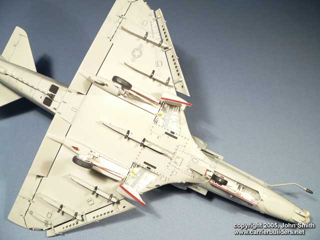
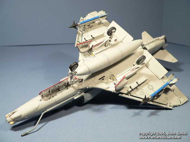
planes was relatively easy with minor modifications. S-Airbrakes were
glued shut, sanded flush and panel lines rescribed.
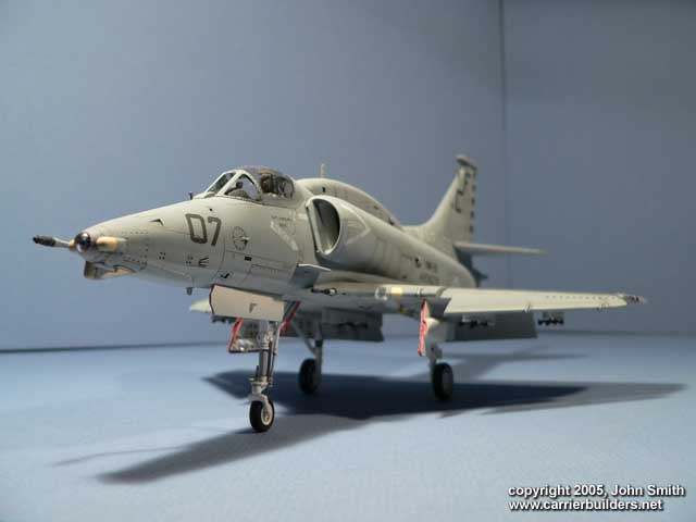
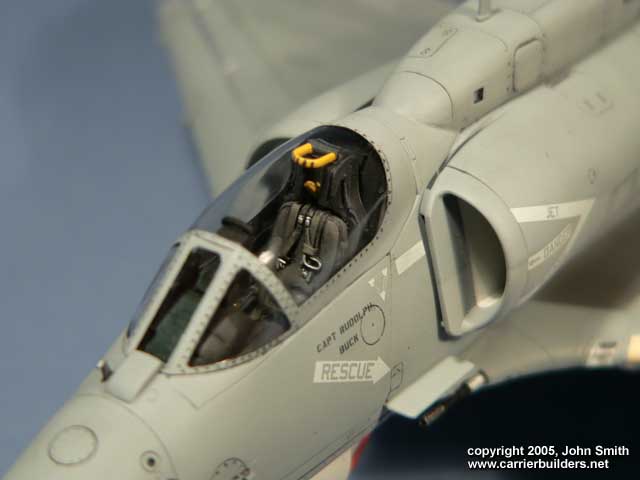
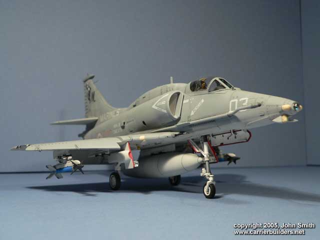
- Ejection seat was replaced with True Details
ESCAPAC seats. These were shaved down on the sides so that they would fit
properly.
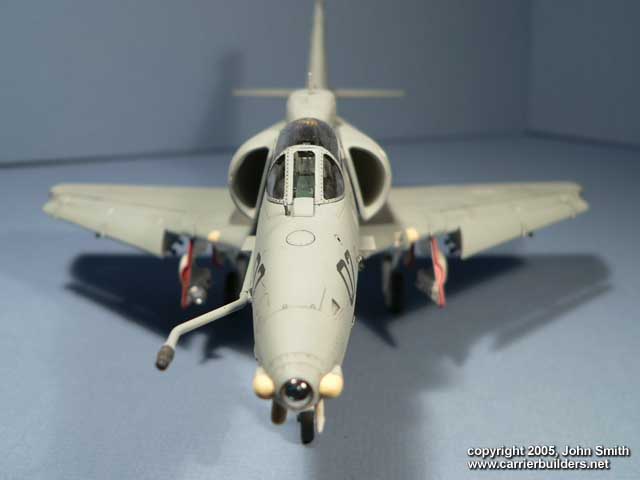
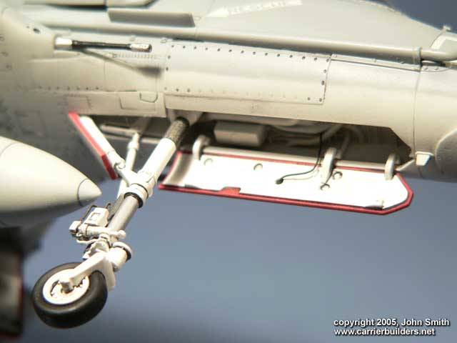
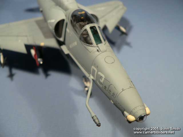
- MV lenses were added on the landing gear doors.-MV lenses glued in nose and
painted over with a mix of food coloring and Future floor polish.
- Centerline fuel tank on VMA-311 plane was acquired from a Hobbycraft A-4M
(Note: I believe I smelted the rest of this kit into a little plastic ingot and
sent it to Hasegawa for recycling cause they would make better use of the
plastic ;^). Modification to this tank included cutting off the end and sanding
out the inside so that it was round and thin at the edge. Flat spare plastic was
cut to size of opening using a digital caliper for measurement. Plastic was
rounded and glued just short in distance from the inner edge of the fuel tank
end so that a lip remained. Holes filled and new one drilled to center tank
properly on it’s respective mounting rack.
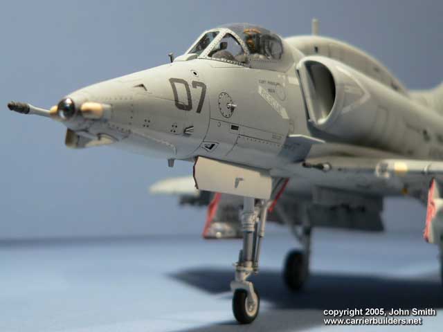
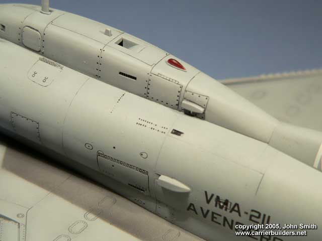
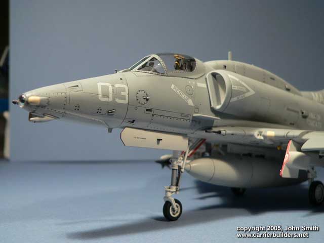
- Dimpled brake fluid level window on nose (port side, right above modex
numbers) with a drill bit and filled with black paint. Hasegawa simply
represents this as small scribed circle but it is actually a small window. -Used
Hasegawa AIM-9’s from their Harrier kit release. Applied Two Bob decals to them.
- Rescribed panel lines where detail was lost seam from sanding.
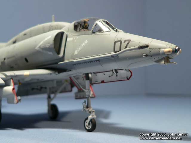
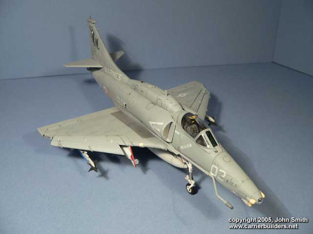
- Cut, replaced and masked landing signal lights lense on port leading edge with
acetate. This looks better than the thick distorted piece given that hides
seeing the lights clearly. This was masked before painting. Area surrounding
light is white with amber, green, and red lenses painted. I used a fine drill
bit to drill these lights lightly refining their shape. A seam line down the
middle makes them look rough.
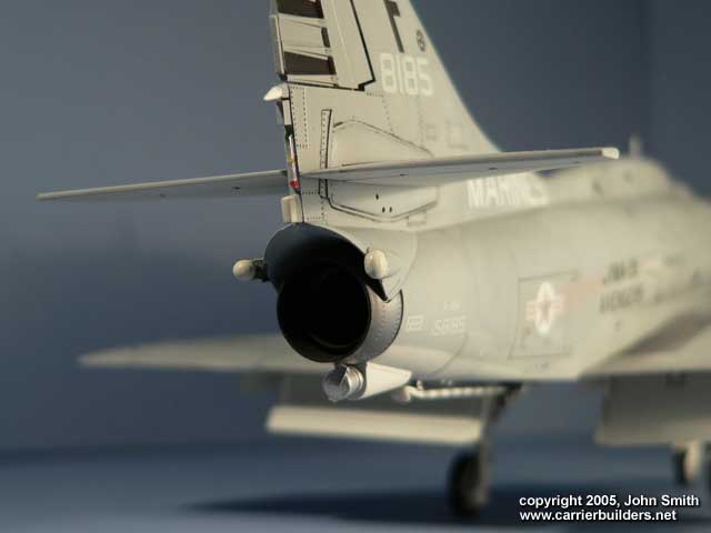
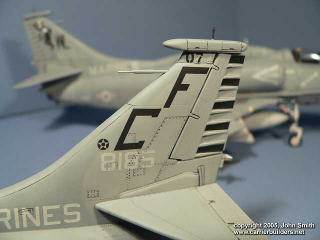
- Pitot tube E20 (included with kit) is placed on
vertical stabilizer. Before gluing the fuselage halves together, clean out the
plug that fills its location point. This replaces part F-24 for those “Mikes”
without this arrangement so check your references.
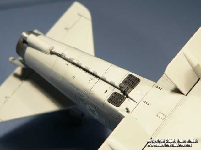
- Extended part F22 with styrene to represent this part more accurately.
Hasegawa supplied these parts originally for the A-4F “SPIKES” on the bottom,
aft of the nose gear, but “Mikes” ALQ-126 antennas were of a different shape
slightly.
- Wiring was added to represent landing gear hydraulics. Nose gear tie-downs
replaced with wire (originally looked like stubs.
- Arrestor hook masked and painted with appropriate number of stripes and
color(decals didn’t cut it here).
Photos and text © 2005 by
John Smith
June 05, 2005
www.carrierbuilders.net |