|
"GUARDIAN OF THE FLEET"
(This title was inspired by the article in Combat Report for
the Gannet)

The need for antisubmarine aircraft was painfully obvious during the
Second World War. With the emergence of the Soviet Union as a global
naval power the need became even more pressing and England quickly
decided to try and fill the void. A combination of endurance and payload
resulted in a need for a new type of powerplant. Armstrong Siddley took
a pair of ASM.3 Mamba engines and mounted them back to back, resulting
in a very compact powerplant with high output. This engine was packed
into the fuselage of the Gannet and contra-rotating propellers were
fitted to the front. This resulted in excellent power for takeoff and
landing, while once in the air the ability to shut down one of the
engines allowed the plane to have a very long endurance.
The Gannet quickly found itself in fleet service, where it performed
admirably. So much so that several countries expressed interest,
including at least two navies that had no ships to operate them from.
The navies of Australia, Germany and Indonesia purchased the Gannet,
putting the Fairey aircraft over just about ever
I
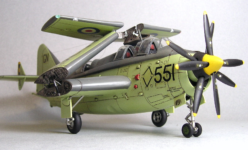
have always wanted to build a model of the Gannet for a long time as I am
especially attracted to its ungainly lines and overall ugly appearance.
Unfortunately, the only kit available (to my knowledge) is the old Frog offering
in 1/72 scale. My preference is building in 1/48 scale and the reviews of the
old Frog kit (lack of wheel wells and pilots’ heads molded into fuselage) put me
off somewhat. While browsing through Hannants website, I came across
Dynavector’s kit of the Gannet in 1/48 scale and placed an online order
immediately (sorry folks, the Dynavector range is temporarily unavailable from
Hannants now, it is indicated in the website that the Dynavector kits will be
produced in Japan).
After several days, my parcel arrived. I was impressed by the sturdy cardboard
box and the no frills box art, which featured a label with a line drawing of the
profile of a Royal Navy AS-1 Gannet and appropriate warning "Not suitable for
Children."
On opening the box, I was most impressed by the quality of the vac-formed and
white metal parts. The vac-formed parts come molded on two sheets (40 thou
thick), with the wings and tailplane components occupying one sheet; and the
fuselage, wheel doors, spinners and other details on the other sheet. Included
is another clear vac-formed sheet with all the canopies and wing landing lights.
Panel lines are recessed and very petite in some areas. I would strongly
recommend that one re scribes the panel lines to enhance their definition. Two
sets of these are supplied, useful if you intend to pose the canopies in the
open position or if you happen to foul up one set during construction. There is
a small bag containing all the white metal parts for the various odds and ends
like the landing gear oleos, wheels, cockpit details, arrestor hook, tail
finlets, exhaust ports, propeller blades etc.. These were quite well molded with
a fair amount of detail although some parts will need careful cleaning up as
some flash is evident.
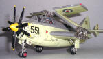
A well printed decal sheet is also supplied and this includes markings for three
schemes, a dark ocean grey/sky Royal Navy version, a dark ocean grey/sky West
German Navy version and finally, an aluminium painted Royal Navy trainer
version. The decals are fairly thin but adequately opaque. Unfortunately, the
roundels were very slightly out of register and this became evident as a thin
white crescent when applied to the dark ocean grey upper wing in the version I
chose to model (more on that later...).
The instruction sheet consists of a single A3 size sheet, printed on both sides.
There are no construction steps but this should not pose a problem as a parts
map is included and the various sketches which show assembly of parts in
relation to one another are more than adequate to aid construction. On the other
side of the sheet, a full scale side view and scrap top/bottom views indicate
placement of decals and other details. The only thing I found inadequate with
the instructions is that no front-on view is included to indicate the proper
orientation of the wing dihedral
I
normally build injection molded kits and this is the first vac-formed model that
I have built in more than ten years and only the third out of the eighty or so
models that I have built to date. I started off construction by deepening all
the panel lines on the major airframe components using Micromark’s excellent
scriber and Dymo tape as a guide. This was done with the parts still attached to
the backing sheet with the exception of those panel lines which needed to go
around the fuselage joint as I was unsure whether these would line up when the
halves were mated later on during construction. I am quite a klutz at scribing
and made several slips during this operation. I corrected several of these
gaffes with super glue and scribed over these areas again once the glue had set.
The scribing was accomplished over three evenings and when I was satisfied with
the results, I marked the edges of the parts with a permanent marker and
proceeded to separate the parts from the backing sheet. I used the time-tested
method of scoring around the edge and gently flexing the backing sheet until
separation was complete. I then taped a 150 grit sandpaper on piece of glass and
wet sanded the part until the thickness of the backing sheet was removed. This
was a much easier exercise than originally envisaged and I completed this task
over the weekend. After this was done, I lightly sanded over the scribed areas
with 600 grit sandpaper and buffed with a Scotch-brite pad to remove any burrs
which might have been formed during the scribing process.
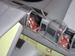
As usual, I started off with the cockpit. This was built per the instructions,
the only additional detailing consisting of lead foil and fuse wire seatbelts.
The cockpit floor and seats were styrene while the instrument panels, side
consoles and the observer’s headrest were white metal. Accordingly, I used cyno
glue exclusively. As no instrument panel decals were supplied, I proceeded to
simulate the various dials as follows. I first sprayed the white metal
instrument panels with white automotive lacquer from a spray can. When this was
fully cured, I sprayed a thin coat of Testors Flat Black. I then used a sewing
needle in a pin vice to gently scrape away the black paint in the areas where I
wanted to simulate the various dials in the instruments. The results were very
satisfactory. The interior was airbrushed flat black and the seats were painted
a reddish brown to simulate the Bakelite material as in the real aircraft (from
my reference photos). After a dry brushing in light grey and chrome silver to
bring out the detail and simulate wear, the various knobs and switches were
picked out with yellow, white and red. The various cockpit assemblies were then
given a light coat of Testors Flat Lacquer from a spray can and then set aside
to dry.
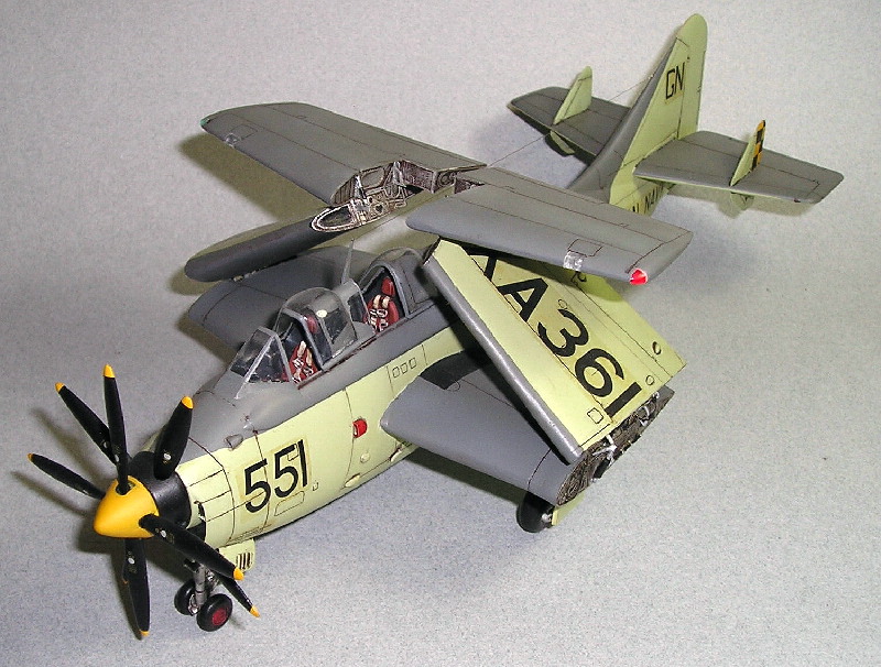
|
Click on the image to enlarge! |
My attention now turned to the fuselage halves. The bulkhead was installed just
aft of the co-pilot’s cockpit. A slot of width corresponding to 40 thou was
opened up in the wing root area just behind this bulkhead. Wing stiffening spars
were fashioned from scraps of the backing sheet and the correct angle for the
slightly inverted gull wing was taken into consideration when making the spar.
My references proved useful in determining this droop. As I decided at the onset
to pose the model with the wings folded, the stiffening spar only extended to
the length of the inboard section of the wing only. The spar was then inserted
through the slot at the wing root and glued to the bulkhead with a generous
application of liquid cement. Once the glue had set, I opened up the areas for
the cockpits and wheel wells. At this stage, the front wheel well and cockpit
assemblies were fitted in the fuselage half. Super glue and liquid cement were
used. To improve bonding when the fuselage halves were mated, scraps of plastic
strips were cemented along the mating surfaces of the port fuselage half. The
halves were then liquid glued and set aside to dry. Once set, the white metal
intake was glued on with super glue. I was debating whether or not to add weight
to the nose despite the indication in the instruction sheet which stated that no
nose weight was required. After some indecision, I decided to go with the
instructions. Filling the area between the white metal intake and the styrene is
a little tricky because of the dissimilar material. I used Milliput for this.
After sanding the joints and rescribing some of the lost detail and the panel
lines which I omitted earlier, the fuselage sub-assembly was finished. Still, I
had this nagging feeling that nose weight was required. To see if the model was
to be a tail sitter, I taped the tailplanes and wings along with the white metal
propeller components to this sub-assembly. I pivoted this whole assembly at the
main undercarriage location and as luck would have it, nose weight was indeed
required. While fiddling around with the fuselage, I managed to drop it on the
floor and the impact separated the intake from fuselage. I used this opportunity
to superglue a flattened out lead fishing sinker on top of the nose wheel well.
After performing the necessary repairs, I set this sub-assembly aside...
At this stage, the tail plane halves were glued and the white metal finlets
attached with superglue. These were then assembled to the fuselage with liquid
cement and reinforced with a length of sprue running along the entire span of
the tailplanes through the fuselage. Slow setting epoxy glue was used to fill
any gaps between the tail plane roots and the fuselage.
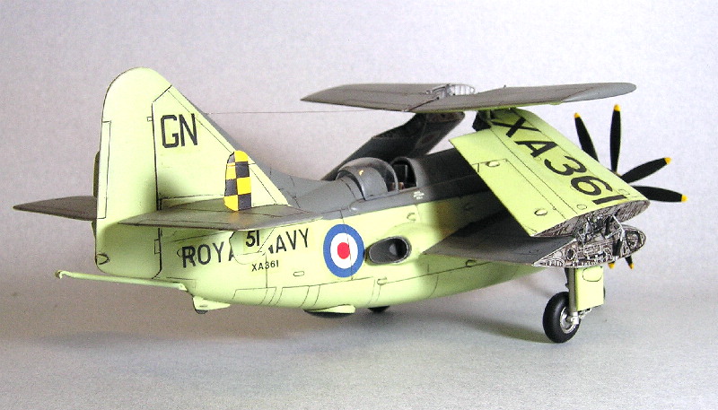
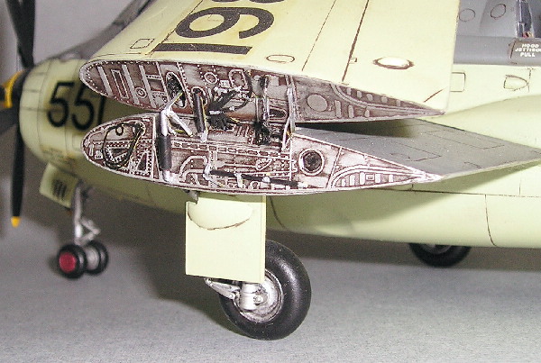
I turned my attention to the wings now. The various sections of the wing folds
were separated according to the instructions in the Airwaves detail set. The
halves were glued together and I proceeded to work on the photoetched wing fold
detail. At this point, I noticed that the wing cross section of the model was
thinner in some areas compared to the phtoetched parts. Cutting the photoetched
parts to fit the cross section was out of the question as this would mean loss
of detail. Since only the middle portion of the cross section seemed to be
thinner, I forced the wing halves apart slightly with scraps of styrene sheet of
the appropriate width. This seemed to help somewhat. After gluing the
photoetched airfoil sections at the wing folds, I further blended the profile of
the wing section to correspond with the photoetched detail using Milliput.
Airwaves does not mention how to hold the wings in the folded position and the
photoetched parts definitely do not have sufficient strength to accomplish this
purpose. After much thought, I came up with the idea of using brass tubing as a
support and embedding the lower piece in a block of plastic just behind the wing
fold detail.
As the wings fold at quite an acute angle, the brass rod will not be very
visible unless under very close scrutiny. I added reinforcement blocks as shown
in the diagram and drilled the mounting holes out as appropriate. The brass rods
were super glued in place and when set, were further reinforced with a generous
application of more super glue and accelerator. The wing tip navigation and the
landing lights were made with green/red and clear scraps of old Oral-B
toothbrush handles. These were superglued in place after first drilling out the
lenses and then sanded and polished with Novus No. 2 plastic polish.
The inner wing section was then glued to the fuselage ensuring that there was a
snug fit with the reinforcement spars installed earlier. More Milliput was used
to fill any gaps at the wing roots. I smoothed out the Milliput as much as
possible with a wet cotton swab and removed any excess with Gunze Mr Thinner.
When set, the wing root was wet sanded progressively with 320 grit and 600 grit
sandpaper. As usual, any loss of panel detail during this process was restored
with my trusty scriber.
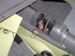
The exhaust fairings were installed next and this proved to be a real bear. A
lot of cutting and trimming was necessary to ensure that they fitted in the
correct position in accordance to the drawings. Again, a generous quantity of
Milliput was needed to ensure that these were faired in correctly to the wings
and fuselage. Installation of the white metal exhaust ports was another
headache. I had to thin down the part and drill through part of the fuselage to
ensure that they fitted correctly within the fairing. Superglue and accelerator
were used to ensure a secure fit.
At this juncture, all the various bumps and lumps on the fuselage and wings were
sanded off and new ones made from plastic scrap. This is actually not necessary
since the original molding is quite good. However during the course of my
earlier sanding, I managed to accidentally damage some of these bumps.
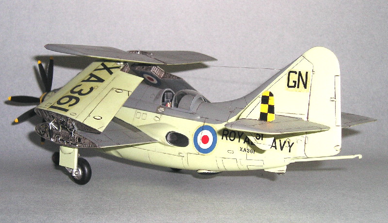
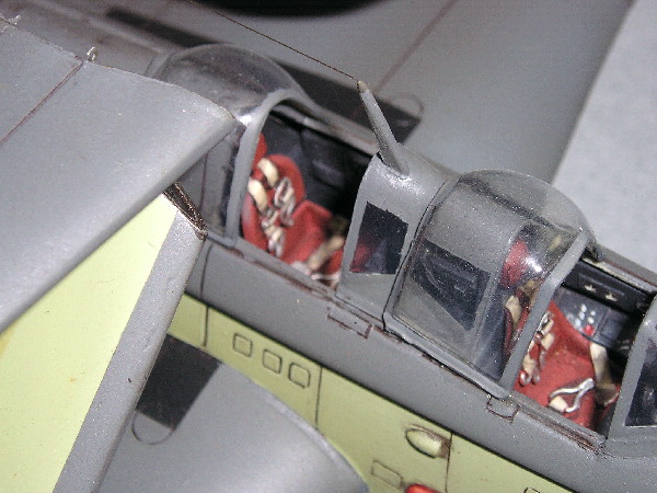
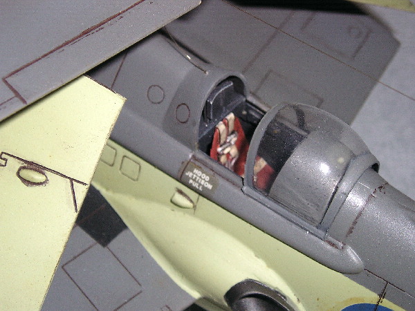
The centre section which separates the pilot and co-pilot’s cockpits comes as a
clear molding. Colour profiles in my references showed that this area was packed
with equipment but I was not sure what this was. Anyway, to create the ‘busy
look’ in this area, I turned to by spares box and packed the area with modified
spares and fuse wiring, what Shep Paine would term as ‘creative gizmology’. When
I was satisfied with the look, I separated the clear molding from the backing
sheet together with the front and rear sliding canopy sections and epoxied this
section in place over the ‘gizmos’
In preparation
for painting, the subassemblies were given a good wash with dishwashing
detergent and a wipe with rubbing alcohol. All cockpit openings, wheel wells and
the clear portion of the centre canopy section was masked off with Tamiya making
tape (great stuff!). The model and the separate wing sections were then given
several layers of Humbrol Neutral Gray as a primer. This was allowed to set for
two days and the various subassemblies were examined for any surface
imperfections. The primer coat was lightly sanded with 1000 grit sandpaper and
all sanding grit and loose dirt was washed off with dishwashing detergent. After
drying out the water on the surfaces and draining out any which might have been
trapped during my over zealous washing, Testors Sky Type S was airbrushed on the
lower wing and tailplane surfaces, and the entire fuselage up to the tail. The
surrounding area around the exhaust pipes were masked off and the exhaust pipe
airbrushed with Testors Metallizer Gunmetal mixed with a touch of non-buffing
Aluminium Plate.
After allowing this
paint to dry overnight, the Sky areas were masked off and Testors Dark Ocean
Grey was sprayed. The masking was removed and any overspray or imperfections was
touched up with a small brush using the appropriate colour. I shot the model
with several coats of Humbrol Glosscote, waited two days for the varnish to set
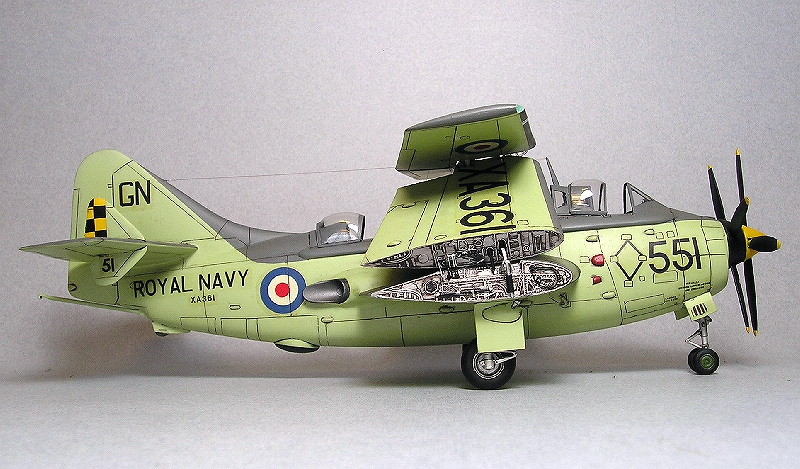
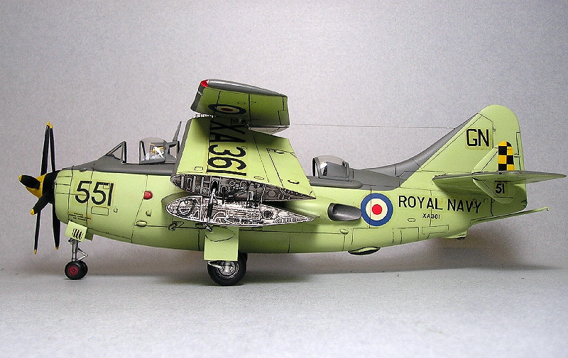
and applied the decals. I chose the Royal Navy scheme over the German Navy one
as the former was more colourful and I especially liked the yellow and black
checkered markings on the finlets. The decals reacted fairly well to Aeromaster
Set and Sol and there were no traces of carrier film once set. However, the blue
and red areas of the roundels were printed slightly out of register with respect
to the white inner ring. This resulted in a white crescent at the edge of the
roundel which was especially noticeable against the dark grey surfaces. I used a
00 brush and touched up this area to the best of my ability and left it at that.
Kitchen cleaner was used to remove any decal glue residue on the model. A
brownish black water colour mix was then applied to accentuate the panel lines.
Once dry, the sub-assemblies were sprayed with Testors Flat Lacquer.
The main details like the
undercarriage legs, prop blades, arrestor hook and wheels were in white metal.
These were cleaned up with a sharp blade to remove seam lines and flash. The
parts were washed and painted and weathered as appropriate. The white metal
antenna mast was grossly undersized and badly misshapen; I discarded this and
fabricated a new one out of a plastic scrap reinforced with a steel wire. I
discovered also that the arrestor gear was too short. According to my
references, the length of the gear should protrude beyond the tail but this was
not the case with the one supplied. I chopped off the hook end and fixed it to
an appropriate length of brass tubing of the correct diameter. All these odds
and ends were painted and attached to the model with superglue. The open
sections of the canopies were attached with white glue. The antenna wires were
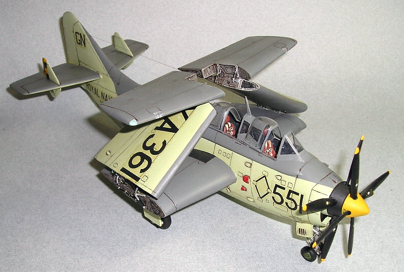
made with very fine, black sewing nylon monofilament. I then epoxied the wings
in the correct folded attitude with slow setting epoxy. This allowed me to make
any adjustments while the glue set. I constructed a jig out of corrugated
cardboard to ensure that the wings were kept at the correct angle while the glue
cured. With all this done, the final stage was to add in all the other wingfold
details like hydraulic lines, linkages and actuators. All these came from the
Airwaves detail set with the exception of the main actuators, which were made
from plastic rod.
I
finished this model over the course of seven months, beginning the project just
after my daughter Emma was born and completing it just shy of her seventh month.
I enjoyed every moment of the project and it proved to be a refreshing change
from the usual injection molded kits which I normally build. The quality of
Dynavector’s kits are truly excellent and unlike other vac-form manufacturers,
everything is supplied so that there is no need for scratch building of
undercarriage legs and cockpits or scrounging around for decals. I highly
recommend Dynavector’s vacforms to any first time vac-form builder, the ease of
assembly is comparable to some injection molded kits and building this kit (or
any other for that matter from Dynavector’s range) would not be beyond the reach
of anyone with some modeling experience. I just can’t wait to start on my Sierra
1/48 Fairey Barracuda….
REFERENCES:
http://www.thunder-and-lightnings.co.uk – This is an excellent website with many
good detail photos of post war RAF and FAA aircraft.
Combat Report Vol. 1 No. 4 May/June 1987
Photos and text © 2005 by
Ewart Yong
April 05, 2005
www.carrierbuilders.net
|