AircraftProfilePrints.com - Museum Quality Custom Airctaft Profile Prints
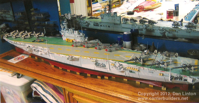
When commissioned in January, 1957, the aircraft capacity of HMCS Bonaventure was listed as 34 aircraft, but it is unlikely that she ever carried that many. At the end of her career the air wing was given as 21 machines. Since her hangar underwent no major changes during her career, and the British practice was to give air wing size as a function of hangar capacity, the figure 34 likely refers to WWII-sized aircraft Work on HMS Powerful was suspended in February, 1945: it resumed again in 1952 when the incomplete hull was purchased by Canada and the ship given her new name. Since three of the four aircraft types used on Bonaventure were far larger than anything found in WWII, then 34 is a misleading figure. But later in her career, a U.S. Navy-style ‘deck park’ was established on the forward flight deck and thus capacity might have been greater than the 21 stated after the 1966-67 refit. In all events, Bonaventure was a small carrier and space on and below the flight deck was always at a premium.
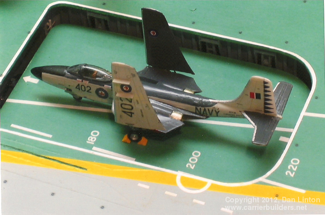
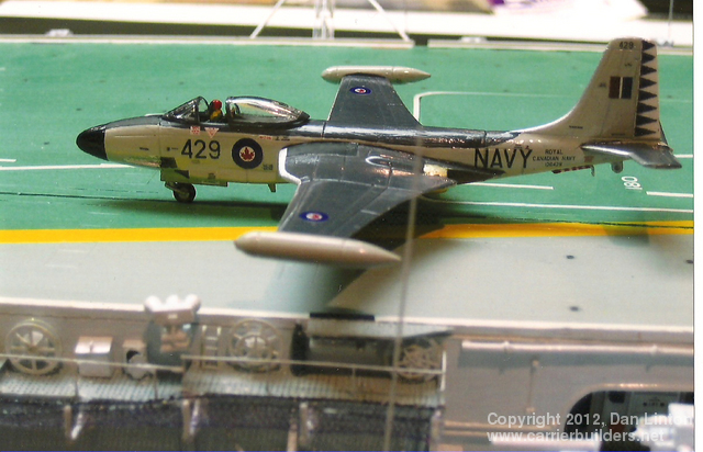
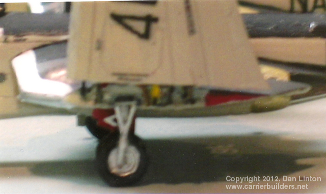
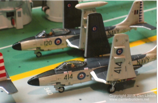
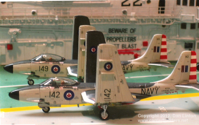
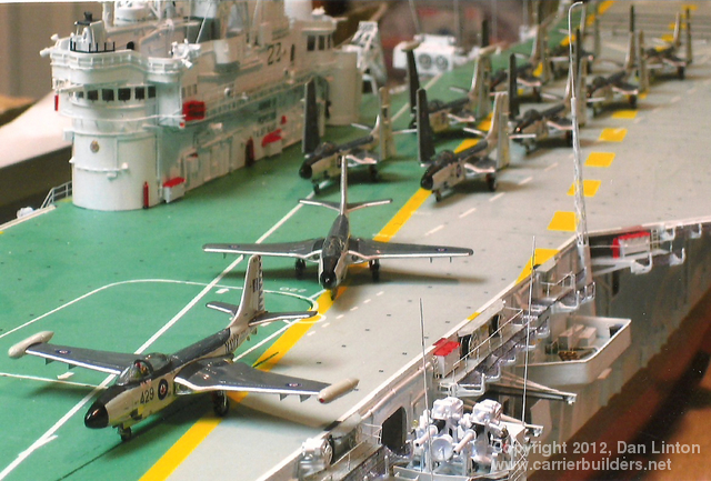
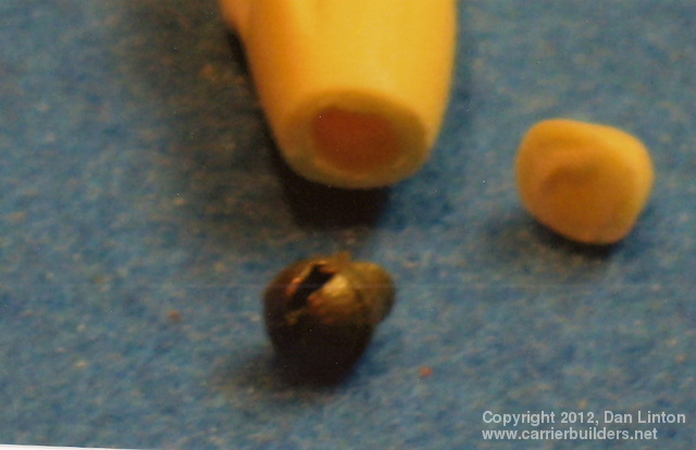
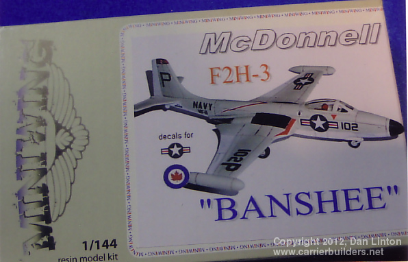
Originally the Canadian government contracted for 62 F2H-3 Banshees. They would cost $½ million each and there would be a payment of $9 million for spares. As it turned out, only 39 were delivered, tired and hard-used aircraft surplus from the USN. The deliveries began in 1956 and were completed in 1958. Two squadrons were established: VF 870 and VF 871. The Banshees were large and heavy. Picture 1 (above) shows how tight the fit was on Bonaventure’s elevators. I produced ten Banshee models, which were resin kits from the small company called Miniwings. Miniwings is owned and operated by Radek Skoumal and specializes in 1:144 short-run kits in resin. They have a very extensive line of kits (www.miniwings.com) : indeed, every single aircraft I produced for the Bonaventure came from this single producer in the Czech Republic. The Banshee had a narrow fuselage and thus was a solid resin cast: no doubt, it would be tail-heavy. Picture 2 shows the kit box and picture 3 shows the noses cut off and a section of the forward fuselage hollowed out to accept a small lead weight. As the aircraft were completed, they were found to be tail-heavy but only marginally. A tiny bit of lead was squeezed into the cockpit and now the models would rest on the front wheel – but blowing on the elevator with mild breath would push the tail back down. For the aircraft that had their wings folded, the problem was solved by gluing wheel chocks onto the wheels. Picture 4 shows all 10 Banshees on Bonaventure’s deck, eight with their wings folded. Picture 5 shows two machines from Squadron 871, identified by their red and white bands on the tail. This squadron was disbanded in the fall of 1959 and its aircraft adsorbed by Squadron 870. Pictures 6,7, and 8 show machines of Squadron 870, noted by the blue and white triangles on the tail. Picture 9, a bit fuzzy, show the attempt made to detail the wing fold mechanism. Only one aircraft has a pilot (picture 10) and two have open cockpits. Interestingly, USN Banshees almost always had tip tanks on the wings but in Canadian usage these were rare, thus they are on only two of the ten Banshees I made. The reason usually given by Canadian Navy spokesmen at the time was that the Banshee already had a long range, so the tanks were not necessary. One document I read, however, stated that the single catapult on the Bonaventure would be overly stressed by the extra weight represented by full tip tanks! Perhaps. The catapult often gave trouble and would be out of service. This was no problem for helicopters, and the Trackers could get off the ship with a long deck run, but the Banshees could not operate on board without a working catapult. In 1959 the Banshees were modified to carry Sidewinder missiles (up to four, two on each wing) but I have never seen a picture of a Sidewinder on a Banshee while the aircraft was attached to Bonaventure. The Banshee was retired in the fall of 1962. Two A4D Skyhawks were tested in 1964 as a potential replacement, but none were purchased. The A-7 was also considered. In the end, the feeling was that a squadron of fighters simply got in the way of Bonaventure’s primary mission – hunting and destroying submarines. Even when available, from 1957 to 1962 Bonaventure would at times go on a cruise or exercise without the Banshees.
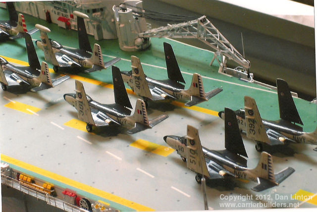
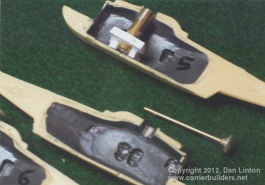
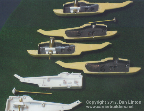
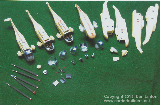
The Trackers: The S2F Tracker was the primary anti-submarine aircraft used on the Bonaventure. The original American version was modified and 99 CS2F-1 and CS2F-2 were built in Canada. The last Tracker built in Canada is seen in picture 11 (above). This one belonged to Squadron VX-10, a test and evaluation squadron. On Bonaventure, Squadrons VS-880 and VS-881 served but as with the Banshees, in 1959 one squadron was disbanded (VS-881) and its machines were taken over by VS-880. VS-881 was originally designated by an ‘A’ on its tail and VS-880 by a ‘B’ (see picture 12) but these letter designations were suppressed when the squadrons combined. After 1959 VS-880 had on its tail gold and black stripes (picture 13); and then simple black stripes (picture 14). I built a dozen Trackers for the Bonaventure model, and they are seen lined up on the deck in picture 15. You don’t have to be very sharp-eyed to notice that all dozen aircraft are sitting on their tails. Suspecting this problem would occur, I began construction of these kits whose fuselage was solid resin by drilling out an area behind the cockpit, putting in a lead weight, and then closing off the area (pictures 16 and 17). The nose could not be effectively drilled out – it was too small and drilling might interfere with the nose wheel-well. Picture 18 shows wires (actually pieces of paper clips) used to help hold on the wings. The kit instructions have the wings butt-glued to the fuselage but I was uncomfortable with that idea and so used the wires for added strength. These wires were also used to establish a secure wing fold mechanism (pictures 19 and 20). Picture 21 shows a Tracker ready to have wings, wheels, props, radio wires and antennas added, prior to painting. The number 566 on a piece of masking tape shows how I kept individual aircraft identified until I could get the correct decals added. And when all the gluing, painting, and decaling was finished – the planes were still tail-heavy.
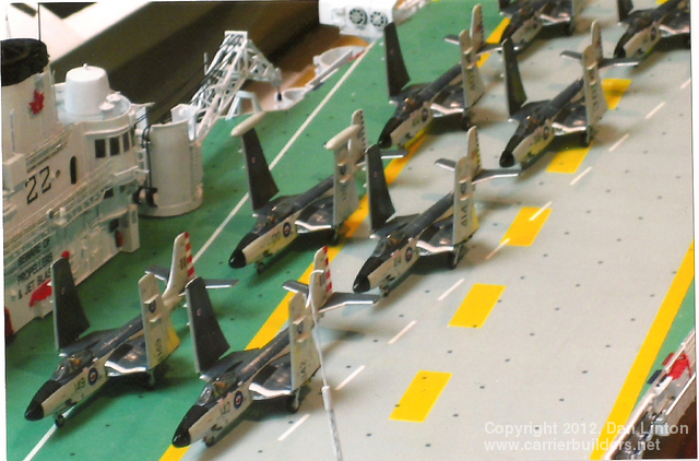
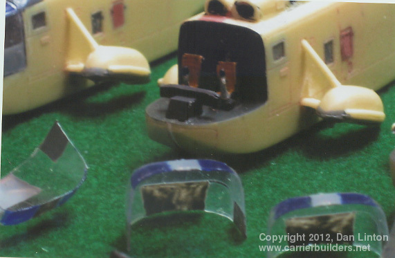
Picture 22 above shows how the problem of being tail-heavy was solved for the nine Trackers that had folded wings. Using wheel-chocks (yellow) glued to the wheels, there was enough flat surface area to push the nose-wheel down. Indeed, aircraft 544 seen in picture 22 seems to be a bit tail high. For the three aircraft without folded wings, wheel chocks were not an option. Picture 23 below shows two deck crew ‘inspecting’ the rear of aircraft 534. Actually, they are literally holding up the tail of the aircraft. This particular machine is one of two taken in hand in 1964 and modified into a COD (Carrier On-board Delivery) aircraft. Picture 24 shows aircraft 574 being attended to by two servicemen while a pilot inspects one of the nacelles. And picture 25 shows two crewmen loading sonobuoys into the chutes at the rear of a nacelle while a pilot looks on. This small scene is based on an actual picture I have – but the real aircraft had its wings folded, chocks in place, and the aircraft is chained to the deck – what I have provided is not realistic (=not safe!) but it does get this machine’s nose wheel down to the deck. Picture 26 shows seven Trackers in a ‘deck-park’ near the bow. This was a frequent arrangement on the Bonaventure, leaving the landing area clear.
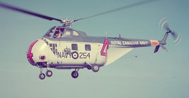
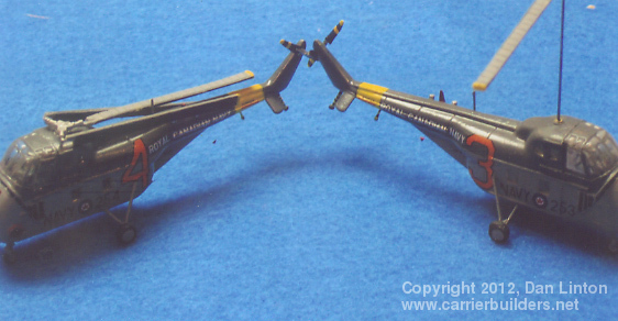
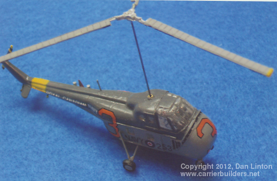
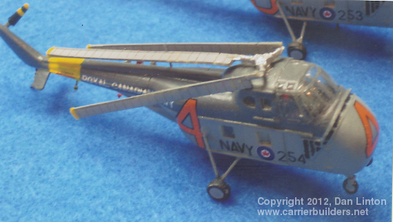
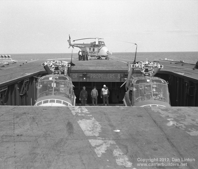
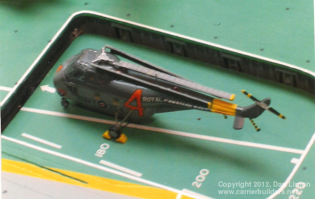
The HO4S, a variant on the Sikorski H-19, was the main helicopter on the Bonaventure from 1957 to 1964 (see picture 27, above). Six or more would be carried in the early years but when the Sea Kings arrived , only one would be left to take on plane guard duties. As seen in picture 28, below, these machines were the smallest of all the aircraft carried by Bonaventure. In fact, they were small enough that two could be transported on a single elevator (picture 29). I built two of these Miniwings kits (these had decals from CanMilAir Decals, as did many of the others), one with folded blades(picture 30) and one with a fully extended main rotor (pictures 31 and 32). At one time I had the idea of a small motor under the flight deck, thus the long wire attached to the rotor hub. This was later cut down when I gave up on the idea of the motor.
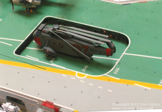
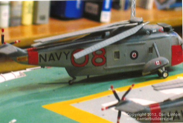
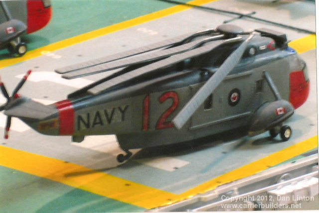
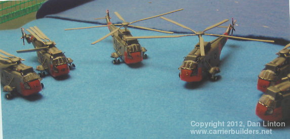
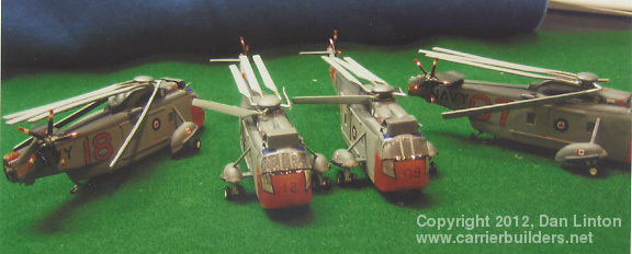
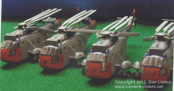
As I write this, in June of 2012, the CHSS-2 Sea King, first delivered in 1964, is still in service in Canada. For a long time now the Sea King has been a joke in bad taste (would you feel confident putting your son or daughter into a 40+ year old car that has had hard usage), the first attempt at replacing it having failed in 1991! But it didn’t begin as a joke. In 1964 the Sea King was modern and powerful and a great asset for the anti-submarine mission. As seen in picture 33 above, the Sea King is a big machine, just managing to fit on Bonaventure’s elevators. Again, the kits came from Miniwings, but are hollow cast. I produced six Sea Kings for the Bonaventure model. Pictures 34 to 38 show these kits under construction. Again, I wanted two of the machines to have rotating main rotors, thus all the work on the interiors – but ultimately, this was not to be. Pictures 39-44 show that four machines have folded main rotors, and two of these also have the tail rotor folded over. As I did with the H04S choppers, I cut the wires of the main rotors so they would sit properly on the helicopters.
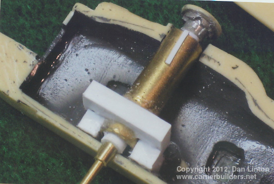
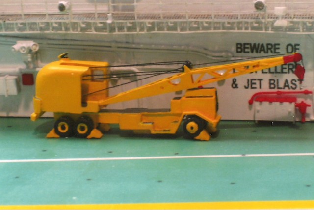
Since WWII, American carriers and those of some other nations, have had a large truck with a derrick crane available, usually parked somewhere on the flight deck. The primary purpose is to be able to remove a disabled aircraft from the landing zone in order to permit air operations to be continued. Bonaventure had the unusual experience of having three different crane trucks within the first three years of its commissioning. Human error or brake failure accounted for the first one – it rolled out and over the flight deck and sank into the ocean. Luckily, the driver jumped out before the truck went overboard. The second truck crane broke down almost the first time it was used to clear a major obstacle – a Tracker landed off the centre line and started to go over the side but was held up by the catwalks, half on and half off the ship. The crane truck was put in position to lift up the Tracker – cables were attached – and the crane truck broke down. Now two immovable machines fouled the flight deck and as no further landings could take place, air operations ceased. Aircraft that had not yet landed were diverted to Halifax as the exercises that Bonaventure was engaged in took place not too far out into the Atlantic. The ship’s captain headed back towards Halifax and planned his arrival there for 1:00 a.m. to avoid any embarrassing pictures. A dockyard crane removed the Tracker and the crane truck. The third and final crane truck was the one I modeled. It is shown in picture 45, above. There were three major components – chassis and motor; cab; and crane – as seen in pictures 46,47, and 48. The finished truck is seen in pictures 49 and 50.
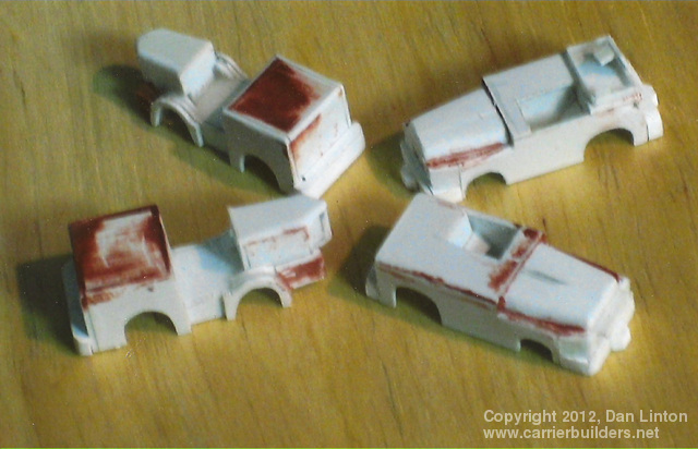
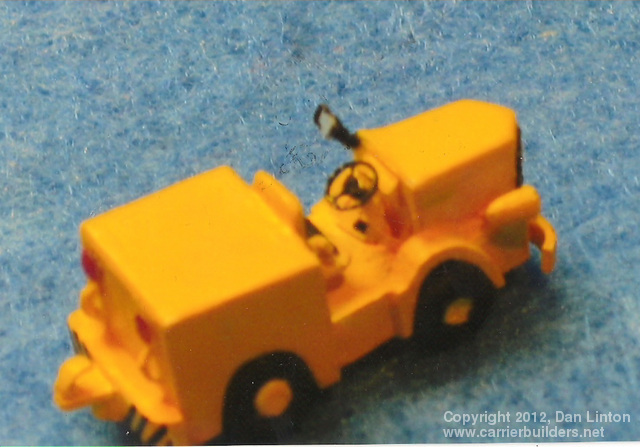
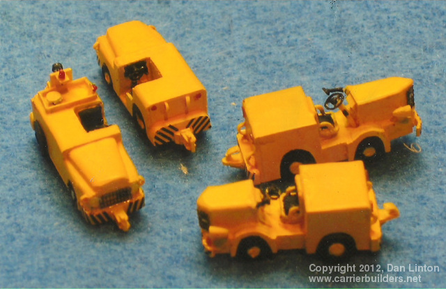
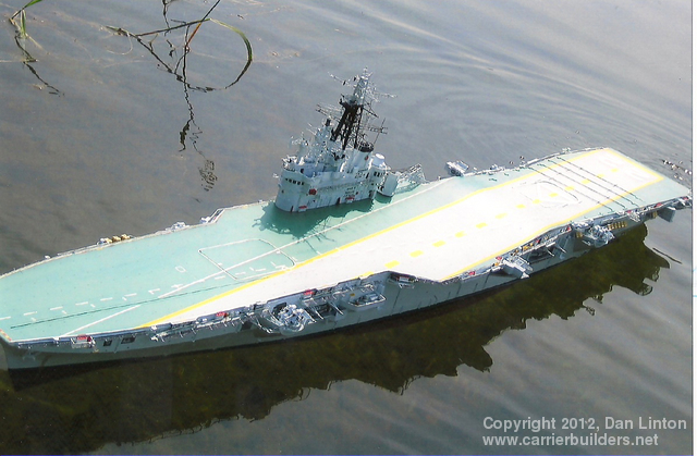
A variety of machines were used on Bonaventure during her career but I had very poor references, particularly for the late 1950’s and early 1960’s. In her last few years Bonaventure had deck tractors that were similar to those being used at the time by the USN. I built four tractors – two ‘early’ style and two ‘USN’ style. Picture 51 shows them about half-way through the build process. Picture 52 shows one of the early style machines – this was based on a single picture I had which only showed the machine from one angle – the rear of the machine was simply guesswork. Picture 53 shows one early style posed beside a much lower USN style tractor. Picture 54 shows all four machines completed, and posed in such a way as to show the front and back of each style. Finally, picture 55 shows the tractors placed on the deck in the most common parking area for them – near and under the ship’s crane. Next: Part 7: On the Water and On Display. The last picture below shows the Bonaventure model the first time it was placed in the water.
Photos and text © 2012 by Dan Linton September 22, 2012 |