AircraftProfilePrints.com - Museum Quality Custom Airctaft Profile Prints
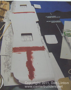
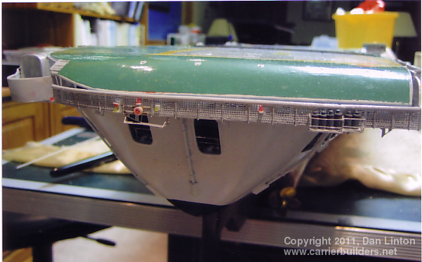
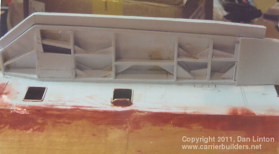
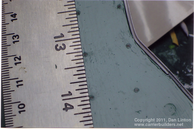
Having decided that the model would have a flight deck that would be removed as a single piece, I chose 60/1000” styrene to provide a smooth but relatively thick surface which would maintain stiffness even after the openings for the elevators were cut out. Pieces of hardwood ½” x ½” (1.27cm) were glued both along the length and across the width of the underside of the flight deck. Two-part epoxy resin was used to glue the styrene to the wood. Picture 1 shows the flight deck (58 9/16” or 1.98m) in its early stage of assembly with the elevators cut out. Notice there are four major pieces with Bondo filler at the joints. The thickness of the styrene would allow the catapult track to be scribed without penetrating through the entire deck and weakening it (picture 2) but that same thickness made problems at the aft end of the flight deck. British carriers (unlike Japanese or American) had a ‘round-down’ at the stern. The ‘round-down’ on the Bonaventure was not as pronounced as on British carriers of the 1930’s but it was still significant enough to create a problem bending the 60/1000” styrene permanently. It kept wanting to return to a shallower bend (note: I would have a similar problem later with the rounded ends of the superstructure). The bend that was finally achieved can be seen in picture 3, even though it is upside down. This picture shows that at the stern, the catwalks had to be attached to the flight deck rather than the hull. Picture 4 shows the catwalks and its support structure – at this stage it is almost finished. Picture 5 shows this area finished. The other area where the catwalks and some safety netting remained attached to the flight deck is at the forward section of the angled landing area. Pictures 6 and 7 show this area during construction from underneath.
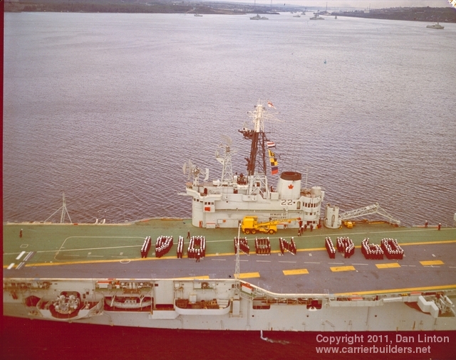
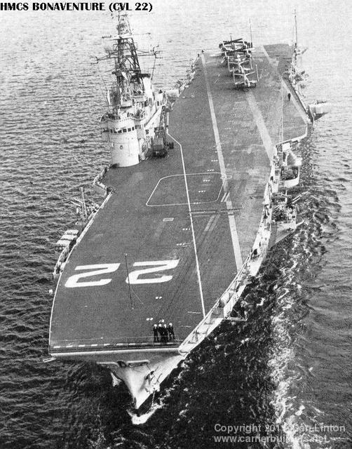
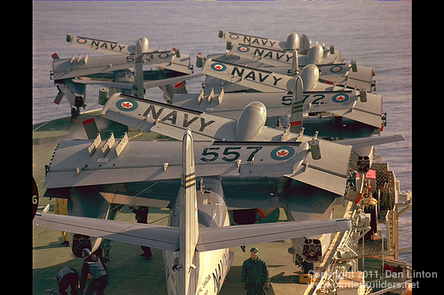
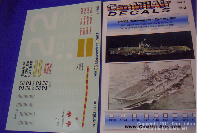
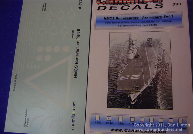
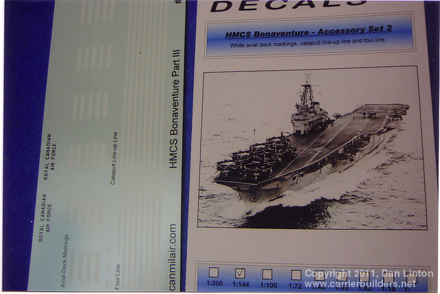
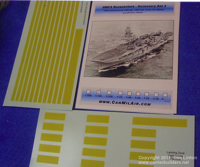
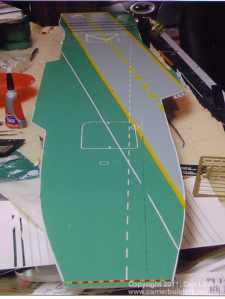
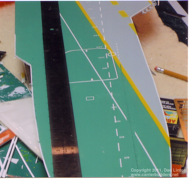
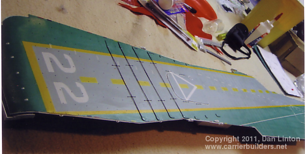
Up until the 1990’s, landing surfaces on Royal Canadian Navy ships (after 1968 officially: Maritime Command) were painted green, as seen in picture 8 above. Bonaventure may well have had the largest surface of any post-WWII warship. Colourful, no doubt, although the brightness of the greens, yellows, and reds faded rapidly in the cold North Atlantic and hot Caribbean areas where the ship spent most of its life both for operations and training. The green was a non-skid formula and was used throughout Bonaventure’s years of service. When launched and for almost the first two years of operation, the pennant number ‘22’ was painted on the flight deck both fore and aft (see picture 9). One of the gentlemen I corresponded with, a former crewman, indicated that the deck crew complained that the forward number ‘22’ was “too slippery” and as this part of the flight deck was the primary parking area for the ship’s Trackers (picture 10), that number was removed. Since I was representing the ship as it was from 1960 to 1965, that number would not be necessary or appropriate, although it was supplied in the decal sets created by Bill Burns of CanMilAir decals (www.canmilair.com) , pictures 11-14. These decals are also available in other scales, particularly 1:400 for modelers who wish to convert the Heller Arromanches kit into the Bonaventure. Picture 15 shows the preliminary painting – the gloss tone would be removed after all the decals were applied with sprays of ‘Dullcote’. Picture 16 shows the beginning of putting on the decals. The catwalks and safety net supports can be seen at the edge of the landing area and the catapult trough is easily visible. Picture 17 has the flight deck decals in place except for some deck-edge indicators (red for fire-hose area; blue for electrical starters) and the aircraft tie-down pad eyes. The pad-eye decals I produced myself: picture 18 shows the pattern and pictures 19 and 20 show these being applied on the flight deck.
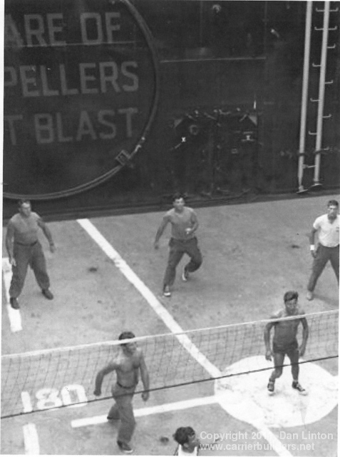
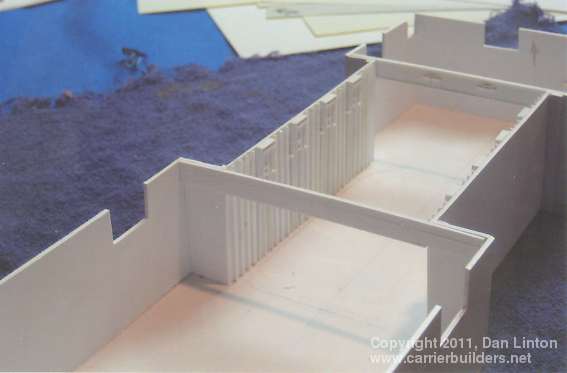
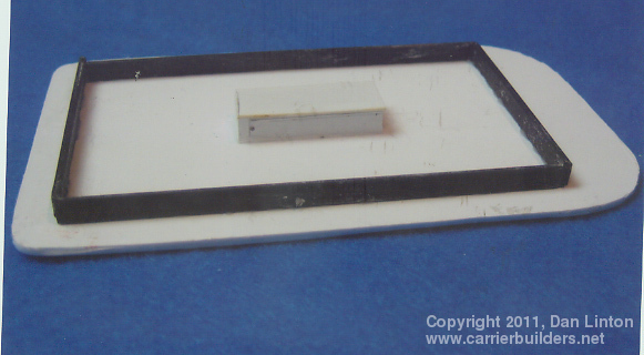
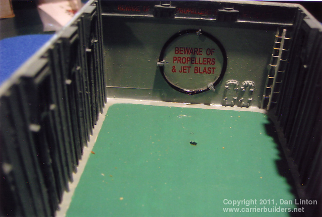
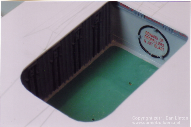
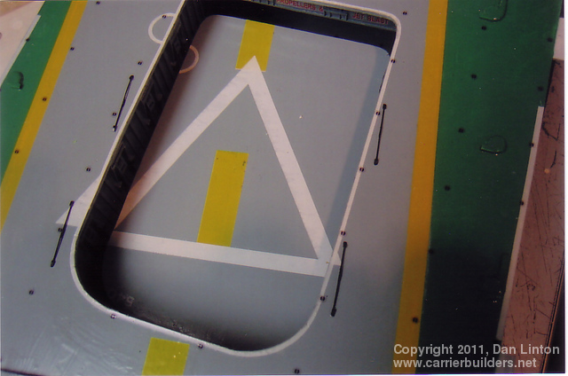
I confess: I have a fear of failure. Despite the fact that Paul Bannon (the gentleman who produced the excellent 1:144 Harry S Truman and the 1:144 HMS Hermes and whose build articles are on this website) not only has sent me diagrams and even an example of a working elevator, I nevertheless did not have the courage to try to make a working elevator for the Bonaventure. The failure to make the hull separate at the waterline discouraged me from being bold in other areas, thus I took the easy way out: I would have elevators that could be displayed as open, closed, or partly open but to achieve this would involve not radio-control but movement by hand. Picture 21 above shows the lowered forward elevator with a volleyball game in progress: the bulwark behind is the most interesting feature because it allows accurate detailing. There were only a few pictures of open elevators available for Bonaventure and one cannot see very far along the hangar so for the model I had two hangar ‘areas’, one per elevator opening. Picture 22 shows the rear elevator area: it has three compartments or sections, the middle one being where the elevator is located. The forward elevator area has two compartments (right of the picture) and the section furthest away at the right is where the elevator operates. Picture 23 shows the forward elevator from about the same angle as the picture above with the crew playing volleyball (note: I am not planning a mini-diorama of a volleyball game in progress). Picture 24 shows the area for the rear elevator. Once the detailing was finished, both these structures were glued to the underside of the flight deck, thus when the flight deck is removed from the hull, so too is the ‘hangar’. No space is gained this way for radio-control equipment but access to and visibility of this equipment is improved. Picture 25 shows the underside of an elevator: the black strips are carbon fibres which give great stiffness and the little white ‘box’ in the middle enclosed a small magnet. Removal of an elevator, normally flush with the flight deck, will be done using a magnet. Picture 26 shows the forward elevator well almost completed and in picture 27 the forward elevator compartments have been glued to the underside of the flight deck. Picture 28 shows the forward elevator in place: note that there are no tie-down pad eyes on these elevators. Picture 29 shows the elevator in its lowered position – except it is no the elevator seen in the previous picture. That piece was removed by a magnet, exposing the elevator well. At the bottom all the decals used on the actual elevator have to be repeated. Note the two holes – these are the guides used when different blocks of wood (balsa to minimize damage) are used to provide different heights, so that the elevator can be displayed in different positions. These can be seen in pictures 30, 31, and 32. The two holes seen when the elevator is at the bottom will normally be hidden by an aircraft or tow tractor placed there. Picture 33 shows the rear elevator in its partially lowered position.
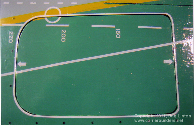
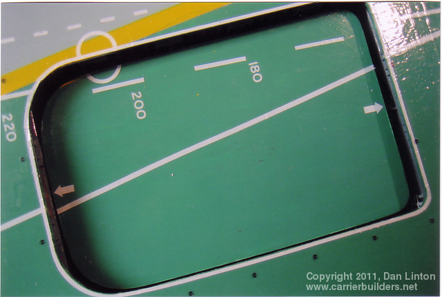
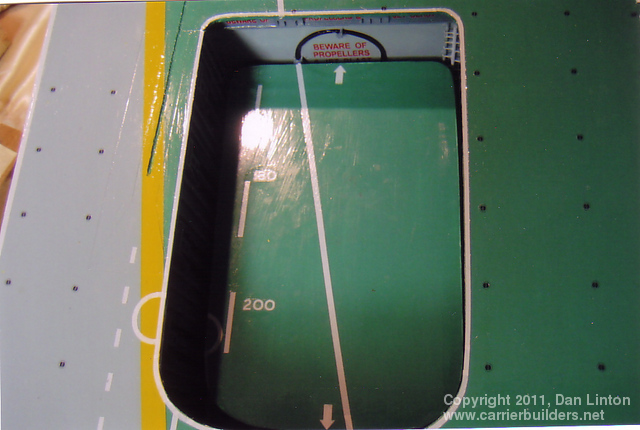
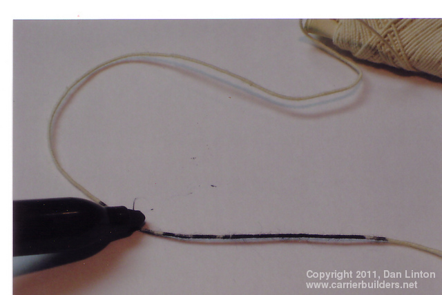
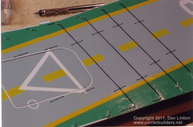
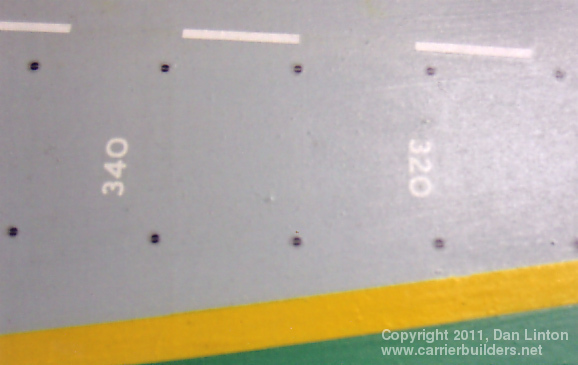
The Bonaventure normally had six arrestor wires to recover aircraft. A seventh wire could be set up but this was rarely used. One problem I had was that in order to display the aft elevator in various positions, the two landing wires that went across the rear elevator could not be set up. One might have created a system to remove/restore those two wires but that would have been relatively complex as the ‘wires’ were actually elastic thread stretched taut to make them appear as wires. Picture 34 above shows this elastic thread, compliments of my wife, being darkened with a black marker pen. Pictures 35 and 36 (below) show the four arrestor wires in place and the springs that keep the wires about 12” off the deck so that tail hooks can be engaged. Picture 37 is interesting because it shows deck markings that measure the flight deck in 20’ intervals (about 6m) and how their orientation changes at the half-way point of the flight deck. Finally, picture 38 (which the sharp-eyed among you will recognize as a repeat of picture 2) shows a red-yellow-red-yellow warning stripe at the bow edge of the flight deck. This strip actually covers small rotating pieces of the flight deck that pop up and act as bumpers to help prevent aircraft from rolling off the flight deck. I have yet to see a picture of these in a raised position. Also, note that the catapult track has no ‘bride extension’ or ‘horn’ for recovering the hold-back strops used with this type of catapult. Unlike almost all other carriers of her class and time period, Bonaventure was never fitted (even after the 1966-68 mid-life refit) with one of these projections, thus every time an aircraft was launched by Bonaventure from her catapult, a ‘strop’ shot forward and sank into the ocean. Next: Part 4: The Superstructure and Masts
Photos and text © 2011 by Dan Linton March 16, 2011 |