AircraftProfilePrints.com - Museum Quality Custom Airctaft Profile Prints
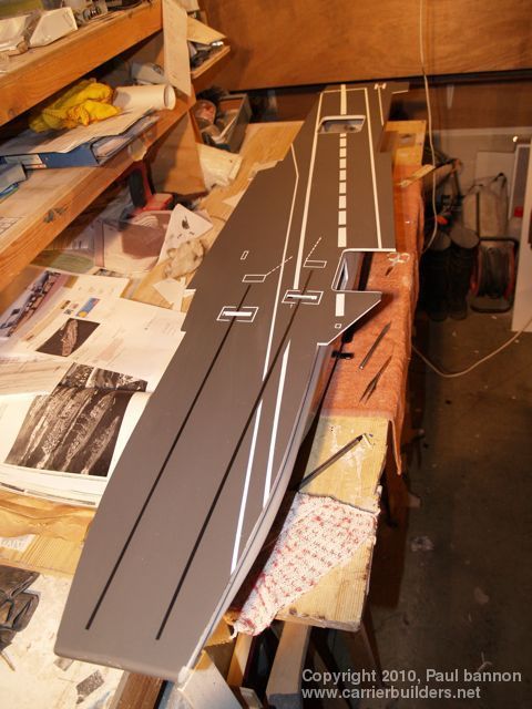
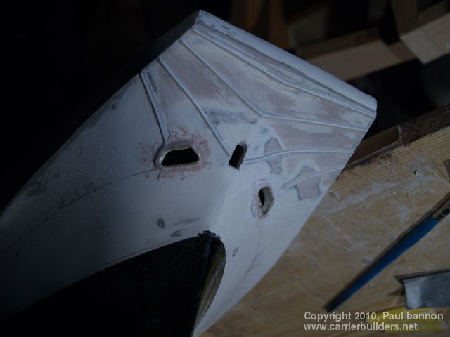
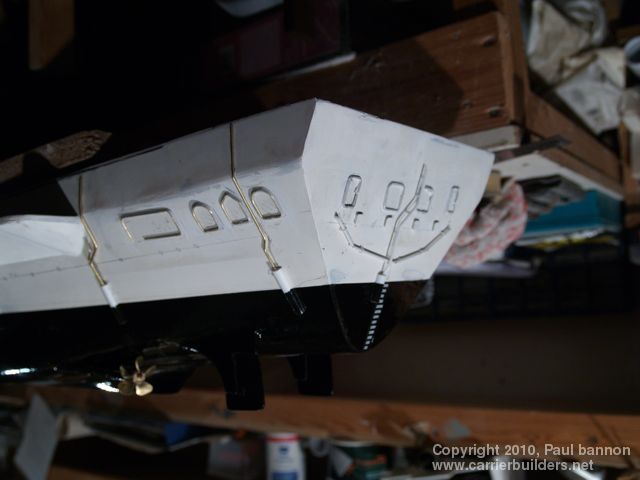
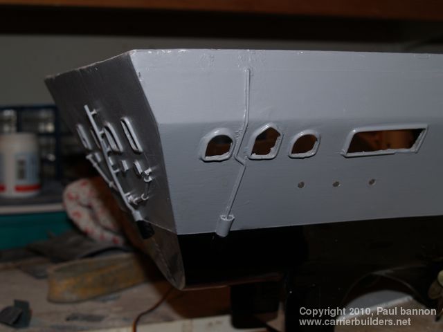
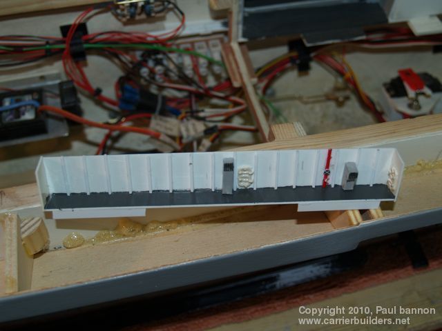
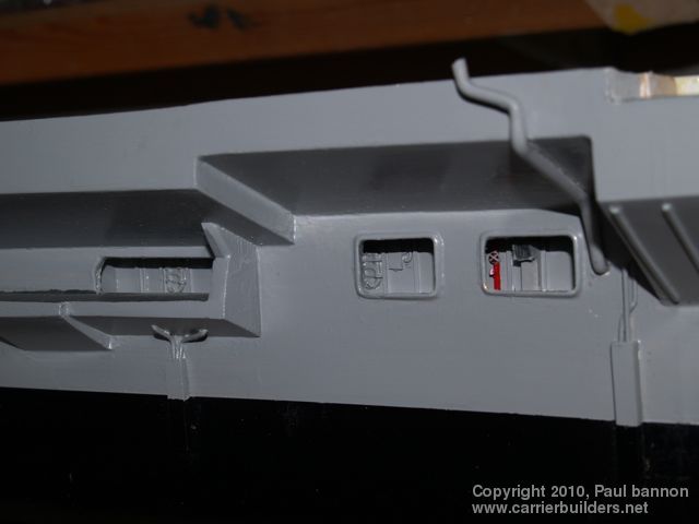
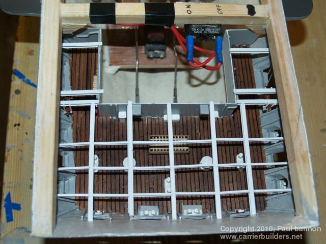
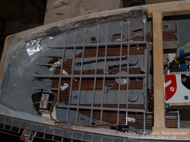
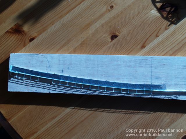
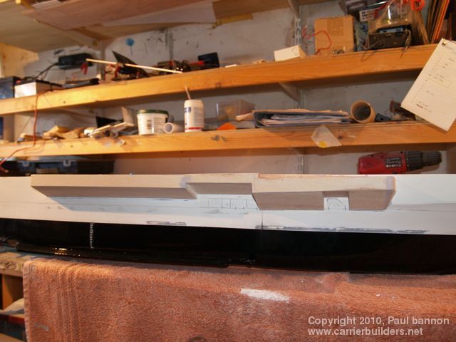
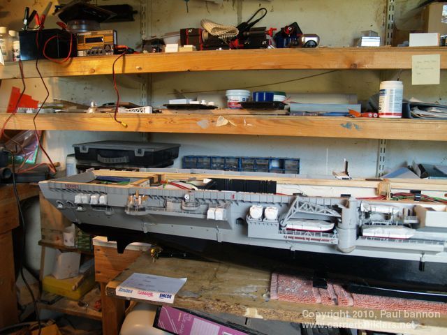
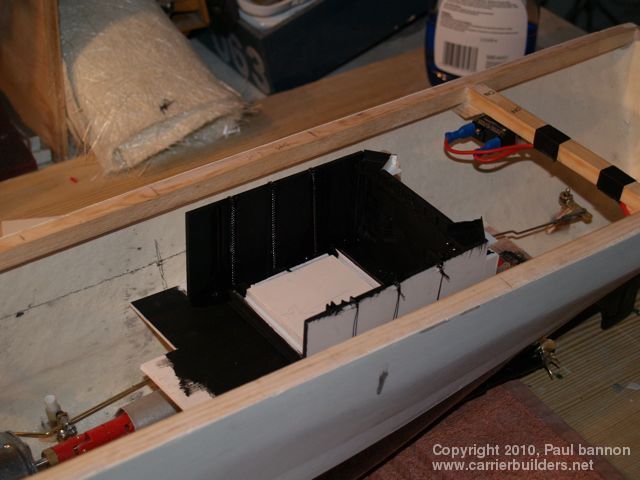
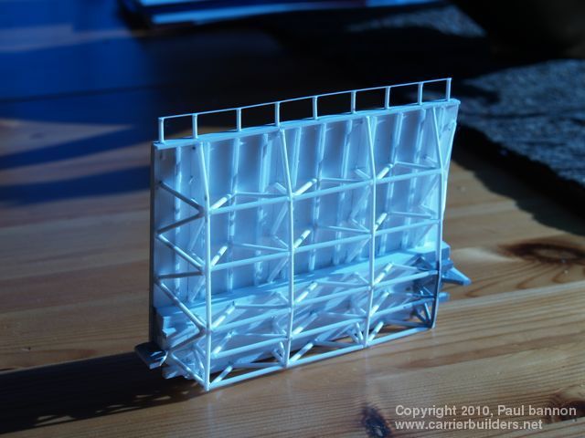
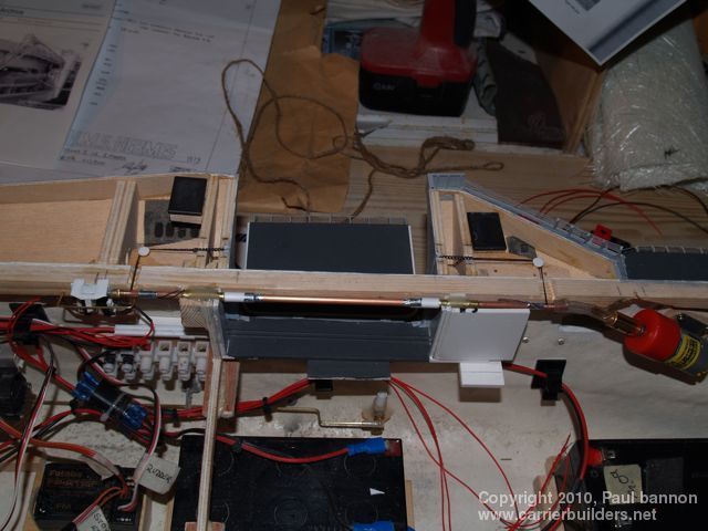
I like to build my sponsons to the Flight Deck, the reverse of the way most people seam to build. If you have accurate plans then building the sponsons first is OK as the same plans will give you a Flight Deck that will fit and look correct. As most of the work on the Hermes has been from pictures and the Flight Deck being the second ( the Hull being the first ) most obvious part of the model, and knowing it’s width then the deck needed to be built first, then sponsons can be adjusted to the deck The Flight Deck is made from plastic as used by professional sign makers and is, I think, expanded foam. It comes in eight foot by four foot sheets so the size of your deck can normally be accommodated. The Hermes deck is about five foot long. It’s easy to cut and sticks to itself or styrene very well with Superglue. All the cut outs were made before work was started on the sponsons and weather decks. At this stage I learned how difficult it is to lay up fibreglass in a consistent thickness. My way around covering this mistake with thick edges to the cut outs was to cut down the inside at as steep an angle away from the opening as possible.Also fitted were the drains that run down the outside of the hull and copper wire around the openings, wich were back filled to give the re enforced look. Having established the shape of the flight deck and having located it by glueing styrene strip to the edges where the deck runs flush with the main hull, effectively creating a ‘lid’ Some basic painting of lines was also done at thi stage. I then began working down each side building the sponsons from a lightweight quarter inch ply and the weather decks from styrene sheet. These were built off the hull, detailed, lit and then fixed in behind the appropriate opening. Quarter Deck and Cable Decks were built in situ, planked, detailed, loose roof girders built up and then a sheet of styrene with lights placed over the girders. The weather decks can be seen but the Cable and Quarter Decks were a little over the top as they cannot be seen from the outside. Cat Walks were also built up off the deck having traced the curve onto some card beforehand. The mesh in the base of these is painted household net curtaining. Many different patterns can be obtained and when sprayed becomes stiff. I should say at this point that wherever styrene had to be stuck to the hull, the hull was sheathed in very thin styrene stuck down with cockpit glue as used by plane modellers. I like to make as much of a model as I can. I know that photo etch can produce some beautiful results and if you are good at soldering ( I am not ) brass wire gives good results. I use Styrene for most of this work. An example is the railings which are made on a small jig. The long runs are laid out through groves over a drawing showing the uprights. These are then cut oversize, the long runs blobbed with glue and the cut uprights put in place. After about 12 hours these have welded solid and the surplus trimmed off. I make one extra rail ie 3 rail is made as 4 rail, the fourth rail is glued down onto the deck - a small amount of extra strength. Ships boats were basically just hulls - at this time almost everything had to have a cover and this makes life so much easier, less detail required ! Life rafts were pieces of dowel with the ends rounded on the lathe, glued into groups of four and covered. All covers are cut from white supermarket plastic bags. On modern vessels you have to show more detail as the rafts are in cases with Hydrostatic couplings - something that was not around in the mid sixties. (Part of my basic training was how to push the life raft into the sea, then find a lanyard to pull to inflate the raft and climb in. Difficult enough in the swimming bath - I never had to try it for real.) Lifts (Elevators ) The system used here was similar to that used on my Truman. All lifts on the Hermes were chain operated - huge bicycle type chains - the aft, centre line lift with four per side and the deck edge lift with one per side. It was not until after the Aft lift was built that i discovered it had four chains per side, up until then I could only see three - so three it is. The chains were from a ladies necklace which as the nearest I could find and in practise only appear on the Aft lift - the run that had to be used on the deck edge lift was to complex and I had to revert to nylon cotton running in black slots. On the aft lift the chains change to nylon cotton after passing over the edge of the lift box and down to the brass tube under the box which is driven by a 1:100 geared motor operating through micro switches top and bottom and a double pole double throw non latching switch, operated by a servo. Small pegs of styrene protruding from the underside of the lift deck catch on the deck and level the lift as it comes to the top. The same principles are used to operate the deck edge lift.. I was anxious to get the warning sound working as the lifts go up and down - the nearest I could find was a cycle bell which you ‘flicked’ each time you wanted it to ring. This was attached to a geared motor with a ‘flicker’ arm that is powered off the lift operating motor.
Lifts (Elevators ) The system used here was similar to that used on my Truman. All lifts on the Hermes were chain operated - huge bicycle type chains - the aft, centre line lift with four per side and the deck edge lift with one per side. It was not until after the Aft lift was built that i discovered it had four chains per side, up until then I could only see three - so three it is. The chains were from a ladies necklace which as the nearest I could find and in practise only appear on the Aft lift - the run that had to be used on the deck edge lift was to complex and I had to revert to nylon cotton running in black slots. On the aft lift the chains change to nylon cotton after passing over the edge of the lift box and down to the brass tube under the box which is driven by a 1:100 geared motor operating through micro switches top and bottom and a double pole double throw non latching switch, operated by a servo. Small pegs of styrene protruding from the underside of the lift deck catch on the deck and level the lift as it comes to the top. The same principles are used to operate the deck edge lift.. I was anxious to get the warning sound working as the lifts go up and down - the nearest I could find was a cycle bell which you ‘flicked’ each time you wanted it to ring. This was attached to a geared motor with a ‘flicker’ arm that is powered off the lift operating motor.
Photos and text © 2010 by Paul bannon December 10, 2010 |