|
Building a 1:144
Scale Radio-Controlled USS Nimitz:
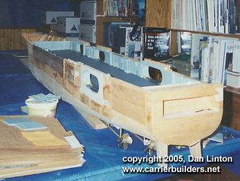
When I built the 1:192 Kennedy long, long ago (think, 1980's) the hangar deck left much to be desired. The pictures that I had of the hangar deck were inadequate, and even when good shots existed, it was difficult to be certain of the exact location -- near the bow? on the port side? The frustrations I see on many websites, including ACB, caused by1:350 kits of Enterprise and Nimitz and the desire of modelers to super-detail the hangar decks reminds me of my own frustrations many years ago. I built in some overhead racks for fuel tanks (for an A-7 squadron) but otherwise the Kennedy hangar deck was more 'generic' (all right -- imaginary!) than accurate. And since it was reached by removing two pieces from the flight deck, and itself was in three pieces for access to the running gear, the idea of a super-detailed hangar deck lost its appeal.
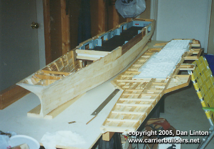
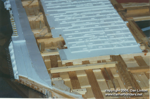
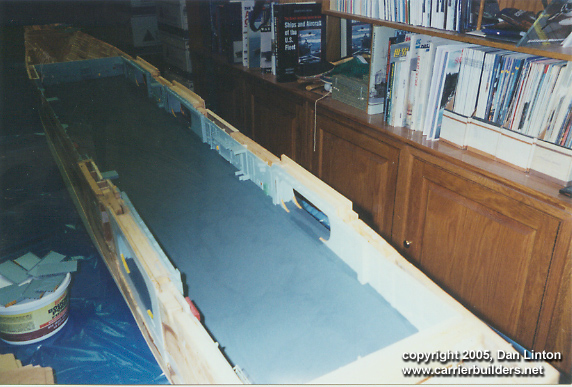
But now I was building a 1:144 Nimitz and it would have the entire flight deck removed (see picture 1). My thinking was that frequent access to the running gear would cause in time warpage and distortions of flight deck sections and soon pieces would not be flush against each other, thus ruining the look of the model. And a single piece flight deck would allow a detailed hangar deck --- but notice I said 'detailed' and not 'accurate'. How detailed should I be?
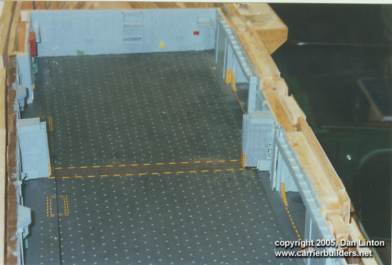
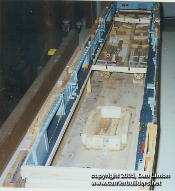
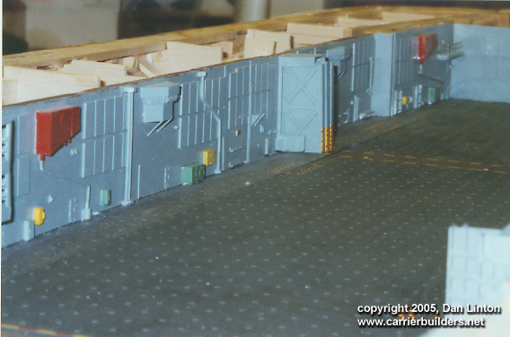
Picture 2 show the doors by an elevator opening (top right-hand corner -- three separate red-yellow warning markers: the two on the left are elevator doors in rolled back position): these can be positioned in open or closed configuration or any position in between but these must be moved by hand. I don't have the skill to use miniaturized motors to open and close these doors. The same is true of the two sets of doors (also in picture 2) which separate the three bays of the hangar deck: a miniature pulley system similar to those used for household drapes is possible, but it would be very delicate and stretch across the area where access is needed for the motors (picture 3).
The further I moved along in the building of the hangar deck, the less ambitious I was becoming. The roof of the hangar deck is a case in point. Between the flight deck and the hangar deck is the gallery deck -- in the case of a 1:144 Nimitz it is more than 3/4 of an inch (approx. 1.8 cm) in depth which is a fair amount of space to stuff in all sorts of lighting and I entertained a vision of lighting the hangar deck and the flight deck (plans for flight deck lighting of post-WWII USN carriers can be found at the Floating Drydock: www.floatingdrydock.com). But look again at picture 1: the flight deck is made of hardwood and pine with some balsa in the empty spaces and is held together with screws and nails as well as glue -- all this to provide rigidity so the entire flight deck ( all 91 inches) can be removed as one piece with minimum bending. The penalty for this? the space for lighting only exists if I were to carve and drill wood to make channels for wires and light fixtures. I balked at this so there is no hangar bay lighting (am I jealous of those modelers who are putting lights in their 1:350 models? Yes).
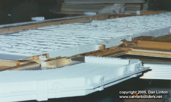
Pictures 4 and 5 show the 'roof' of the hangar bay. Details are somewhat difficult to see as it is all white styrene painted matt white. The rest of the hangar bay walls have been painted haze gray but they should also be matt white: I will correct this mistake before the ship is completed. The hangar deck was begun more than four years ago and it wasn't until late last year that I found out the proper colours for the hangar deck.
Pictures 6 and 7 show some details -- the fire control stations are accurate as to shape and size (still need tinted windows) and their locations are not too inaccurate. The best source I had was a two page spread (pp.14-15) in Concord Publications USS Abraham Lincoln but as the pictures were in black and white, then colours were guesswork. Many of the warning signs are missing, again because the colour is unknown and can't be guessed accurately from black and white photos. I wondered at the apparent lack of fire hoses but these must mean great confidence exists in the sprinkler systems these hangar bays have.
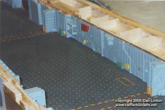
Pictures 8 and 9 show the hangar deck before I put in decals for the tie-down
pads. The colour used for the deck was 'Panzergrau', the closest thing to
the correct FS 36173 that existed at the time. Now correct colours are available
from WEM but I will use them for the flight deck: I am not going to re-paint the
hangar deck. Pictures 2, 6, and 7 show the decals I used for the tie-down
pads. The alternative to decals would be to punch depressions in the plastic ( I
do have a punch set) and then put in PE tie-down pads, but no one makes them in
this scale and the cost of a custom order would be overwhelming (the PE for the
flight deck walkways is bleeding me - but more about that in Part VI). I will
learn one day to make my own PE but it won't happen for this project. So decals
were the alternative and I turned to Mike Grant (www.mikegrantdecals.com).
Luckily, this was only a few months before Mike stopped taking custom orders. I
sent Mike scans of tie-down pads seen in an issue of Koku-Fan and he sent to me
test strips (about 8 pads each) of three different 'brightness' of pads: I chose
the middle of the three. Everyone knows that it is not long into a cruise before
the pads lose colour and begin to blend in with the flight deck -- but before
Go to: Photos and text © 2005 by Dan Linton June 18, 2005 |